


7
Proceed to the instructions within this manual relating 9.
to the repair being performed - see Table of Contents
for page number.
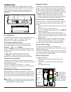
INSTRUCTIONS FOR REMOVING FROM
WALL
WARNING: Disconnect power before attempting any
maintenance or cleaning to reduce the risk of electric
shock or damage to persons.
CAUTION: If unit was operating prior to servicing allow
at least 10 minutes for lights and heating elements to cool
off to avoid accidental burning of skin.
!
NOTE: Only required for replacement of the power
cord or removal from service.
CAUTION: Follow “Preparation for Service” instructions
before proceeding.
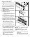
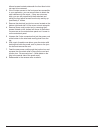
Mounting - The replace may be mounted in one of 3 meth-
ods:
Surface Mount•
Recess Mount (partially in the wall)•
Flush Mount (completely in the wall)•
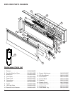
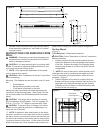
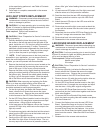
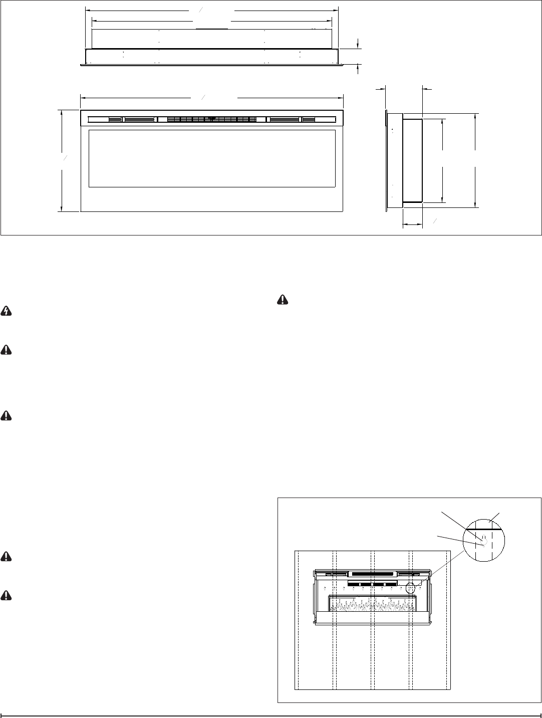
Identify the type of mounting and follow the appropriate
instructions in the following pages. (See Figure 6 for the
top and side prole view with measurements of the back
panel).
CAUTION: Two people will be required for removal
and re-installation of the replace. The unit is approx. 50
5/16”w x 19 1/2”h x 7”d. Weight is approximately 75lbs.
CAUTION: To prevent injury or damage, turn off the
breaker in your electrical panel prior to attempting to re-
move this unit off the wall.
!
NOTE: If replace is hard wired directly to the electri-
cal panel, and there is not enough slack in the wires within
the wall to reach your work area, remove the electrical junc-
tion box cover located on the bottom right by removing the
1 screw on the front of the cover. Lift the cover off and set
aside. Disconnect the 3 wire connectors connected to the
power source, taking note of their original conguration.
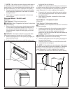
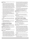
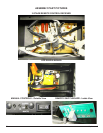
Surface Mount
(Figure 7)
Tools Required: Philips head screwdriver
CAUTION: Follow “Preparation for Service” instructions
before proceeding.
Partially unscrew the rear mounting screws that are 1.
holding the replace to the wall along the back panel
of the unit. Support the weight of the replace when
loosening the screws so unit does not fall off the wall
unexpectedly.
!
NOTE: Be sure to take note of which keyhole mount
openings were used for positioning the replace so that
it can be re-placed in the same location when service is
complete. (Figure 7)
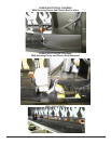
Take the replace off the wall by carefully lifting the 2.
replace off the mounting screws so they line up to the
larger part of the keyhole openings and pull forward.
Carefully lay the unit down on a solid at surface with
the front of the unit facing up.
50
5
16
" (128 cm)
19
1
2
(49.5 cm)
46" (116 cm)
48
1
2
" (123 cm)
3" (7.6 cm)
7"
(17.8 cm)
3
13
16
"
(9.7 cm)
18"
(45.7 cm)
16"
(40.6 cm)
Figure 6
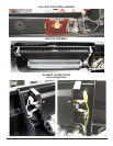
Figure 7
Key-hole
Wall stud
Permanent
mounting hole