


12 www.dimplex.com
!
NOTE: Note the orientation of the switch prior to
removing.
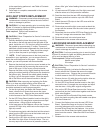
From the front of the panel, insert new switch by push-5.
ing switch back through the hole past the side tabs on
the switch, securing it in the opening.
Reconnect wires onto the prongs at the back of the 6.
switch in their original conguration.
Reassemble in the reverse order as above.7.
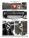
REMOTE SWITCHBOARD
REPLACEMENT
WARNING: Disconnect power before attempting any
maintenance or cleaning to reduce the risk of electric
shock or damage to persons.
CAUTION: If unit was operating prior to servicing allow
at least 10 minutes for lights and heating elements to cool
off to avoid accidental burning of skin.
Tools required: Phillips head screwdriver.
Needle nosed pliers
Wire snips
CAUTION: Follow “Preparation for Service” instructions
before proceeding.
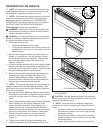
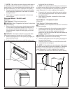
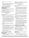
Remove the 4 screws that secure the angled switch 1.
housing cover located just below the Remote Switch-
board on the top right. Remove cover and set aside.
Remove the front panel that spans across the top front 2.
facia. To do so, locate the 4 screws: 2 on the left and
2 right on the angled part behind the facia. Wires from
the switch housing are connected to this piece so care-
fully rotate it up 180 degrees and move it farther down
in the body of the unit, to give some room for access.
This will make the switch visible from behind.
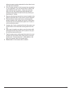
Disconnect the wiring connections noting their original 3.
locations.
!
NOTE: Using a at head screwdriver gently pry
between the end of the connectors and the switchboard to
release the wires.
To remove the switchboard off the plastic mounts, cut 4.
or pinch the plastic mounting tabs with snips or needle
nose pliers. Pull the old board off.
Push the old mounts out towards the front/top of the fa-5.
cia panel. Insert and push the new mounts all the way
through into the same opening. Line up the holes on
the switchboard and gently press the new board onto
the mounts. Make sure the board is secure.
Reconnect the wires onto the back of the switchboard 6.
in its original conguration. .
Reassemble in the reverse order as above.7.
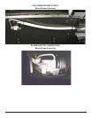
REMOTE CONTROL RECEIVER
REPLACEMENT
WARNING: Disconnect power before attempting any
maintenance or cleaning to reduce the risk of electric
shock or damage to persons.
CAUTION: If unit was operating prior to servicing allow
at least 10 minutes for lights and heating elements to cool
off to avoid accidental burning of skin.
Tools required: Phillips head screwdriver.
Needle nosed pliers.
Wire snips
CAUTION: Follow “Preparation for Service” instructions
before proceeding.
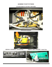
On the top right side of the back panel, just below the 1.
manual control switches, remove the 2 screws that se-
cure the upper control panel cover. Remove the cover
and set aside to allow access to the Remote Control
Receiver wires (the board is the larger circuit board on
the left).
Remove any plastic cable ties to allow for easier re-2.
moval of the wires on the Remote Control Receiver.
Remove the wires off the Remote Control Receiver, 3.
taking careful note of the original location of the wires.
!
NOTE: Using a at head screwdriver gently pry be-
tween the end of the connectors and the receiver to release
the wires.
!
NOTE: Some of the wires may have a “piggy-back”
connector that allows a second wire to connect to the same
prong as the rst wire. Try and keep the “piggy-back”
connection together when pulling the wires off the Remote
Control Receiver.
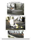
To remove the Remote Control Receiver off the plastic 4.
mounts, pinch the plastic mounting tabs with needle
nose pliers. Pull the old board off.
Attach the rebox wires onto the new Remote Control 5.
Receiver. Spread the ange on the top of the plastic
mounting tabs apart and re-use them to re-secure the
new Remote Control Receiver into the rebox. Line up
the holes on the Remote Control Receiver and gen-
tly press the new Remote Control Receiver onto the
mounts - making sure the board is secure.
Reassemble in the reverse order as above.6.
POWER CORD REPLACEMENT
WARNING: Disconnect power before attempting any
maintenance or cleaning to reduce the risk of electric
shock or damage to persons.
CAUTION: If unit was operating prior to servicing allow
at least 10 minutes for lights and heating elements to cool
off to avoid accidental burning of skin.
Tools required: Phillips head screwdriver.
Needle nosed pliers.
CAUTION: Follow “Preparation for Service” instructions
before proceeding.
CAUTION: Follow “Instructions from Removing from
Wall” before proceeding.
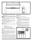
Partially release the lower face panel. There are 5 1.
screws in total are holding the panel: 1 screw on the
left and 1 on the right, inside the unit. There are 3 ad-