


6 www.dimplex.com
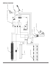
PREPARATION FOR SERVICE
!
NOTE: All components are replaceable from the front
of the replace while the unit is mounted on the wall, with
the exception of replacement of the power cord.
!
NOTE: If the power cord needs replacing or if the unit
needs to be removed from the wall for any other reason
please begin service by following the “PREPARATION
FOR SERVICE” instructions, then move on to the section
“INSTRUCTIONS FOR REMOVING FROM WALL”.
Tools Required: Philips head screwdriver
WARNING: Disconnect power before attempting any
maintenance or cleaning to reduce the risk of electric
shock or damage to persons.
CAUTION: If unit was operating prior to servicing allow
at least 10 minutes for lights and heating elements to cool
off to avoid accidental burning of skin.
Disconnect power source. 1.
Unplug the replace from the outlet. •
If unit has been hardwired for power or outlet is not •
accessible from the front, turn the breaker off at the
electrical panel.
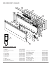
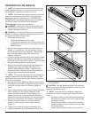
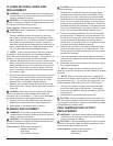
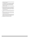
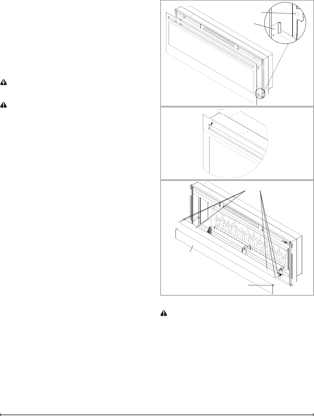
Remove the front glass assembly by removing the 2 2.
screws (1 on the left and 1 on the right side, located
just inside the top front vent opening). These screws
secure the front glass panel to the inside of the
replace. (Figure 4)
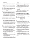
Lift the front glass assembly off of the 4 mounts located 3.
between the outer and inner casing of the replace: 2
on the left and 2 on the right. (Figure 3) Carefully place
the glass assembly aside in a safe location.
Remove the decorative glass ember-bed pieces from 4.
the media tray, which lies along the bottom of the
interior Partially Reective Glass. A medium sized
container such as a bucket or a box will be needed to
keep the glass ember-bed pieces together.
!
NOTE: Try to ensure the pieces do not get pushed or
wedged underneath the Partially Reective Glass. They
may obstruct the ease of removing the Partially Reective
Glass from the replace.
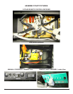
Remove the Partially Reective Glass by removing the 5.
2 screws on each bracket; (2-brackets in total), located
on the left and right side of the Partially Reective
Glass.
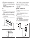
With one hand gently supporting the Partially Reective 6.
Glass, carefully pry the Partially Reective Glass
forward from the upper half so that it begins to tilt
forward from the top. Grasp the Partially Reective
Glass from the sides and carefully lift it up and out from
the front of the replace. Set it aside in a safe place.
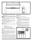
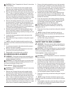
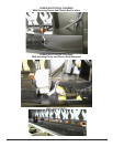
Remove the plastic media tray by removing the 6 7.
screws: 3 on the left and 3 on the right of the tray.
(Figure 5)
The tray has a small lip that goes underneath and 8.
slightly up behind the Partially Reective Glass - from
the front edge, pull the tray up and forward to take it out
of the replace.
CAUTION: Partially Reective Glass is not tempered.
Do not bump or drop the Partially Reective Glass to avoid
breakage and personal injury.
!
NOTE: Once the repair is completed, replace the
media tray rst before re-inserting the Partially Reective
Glass.
Re-place 1 screw on both the left and right side of •
the media tray closest to the front to align the tray
and keep it in place.
Put the Partially Reective Glass with the rubber •
protective strip at the top and secure with the side
mounting brackets
Secure the remaining 4 screws in the media tray.•
Figure 4
Tab
Figure 3
Hooks (4)
Mounts (4)
Figure 5
Front Panel
Front Panel tabs (2)
Media Tray screws (6)