


8 www.dimplex.com
!
NOTE: If the surface you are using as a work area on
is a nished surface that is prone to scratches (i.e. hard-
wood ooring), it is recommended that a protective barrier
be used underneath, (i.e. cloth, cardboard, thick plastic).
Proceed to the instructions within this manual relating 3.
to the repair being performed - see Table of Contents
for page number.
Once repair is complete, reassemble in the reverse 4.
order as above.
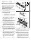
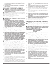
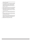
Recessed Mount - Partial In-wall
(Figure 8)
Tools Required: Philips head screwdriver
CAUTION: Follow “Preparation for Service” instructions
before proceeding.
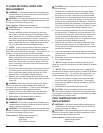
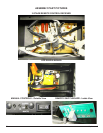
Remove the 4 mounting screws located approximately 1.
3 inches deep in the space between the outer and in-
ner casing on the left and right hand side. There are
2 screws per side, upper and lower going into a stud.
(Figure 9)
CAUTION: The replace should be supported while
removing the screws to prevent the unit from falling.
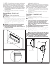
Remove the replace out of the opening by slightly lift-2.
ing and pulling forward.
Carefully lay the unit down on a solid at surface with 3.
the front of the unit facing up.
!
NOTE: If the surface you are using as a work area is
a nished surface that is prone to scratches (i.e. hardwood
ooring), it is recommended that a protective barrier be
used underneath, (i.e. cloth, cardboard, thick plastic).
Proceed to the instructions within this manual relating 4.
to the repair being performed - see Table of Contents
for page number.
Once repair is complete, reassemble in the reverse 5.
order as above.
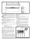
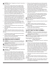
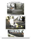
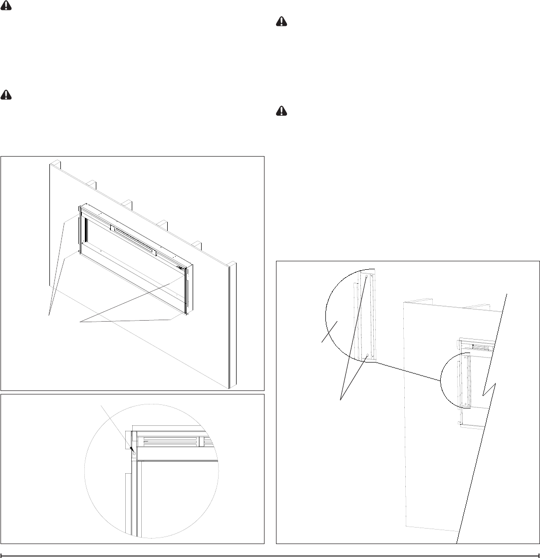
Flush Mount – Complete In-wall
(Figure 10)
Tools Required: Philips head screwdriver
CAUTION: Follow “Preparation for Service” instructions
before proceeding.
Locate and remove the 4 mounting screws inside the 1.
unit located on left and right side towards the front.
There are 2 screws per side, going from the side
panels out into the side of the wall stud that frames the
replace. (Figure 10)
CAUTION: The unit should be supported while remov-
ing the screws to prevent the unit from falling.
Remove the replace out of the opening by slightly lift-2.
ing and pulling forward.
Carefully lay the unit down on a solid at surface with 3.
the front of the unit facing up.
!
NOTE: If the surface you are using as a work area is
a nished surface that is prone to scratches (i.e. hardwood
ooring), it is recommended that a protective barrier be
used underneath, (i.e. cloth, cardboard, thick plastic).
Proceed to the instructions within this manual relating 4.
Mounting Holes
Figure 8
Mounting Holes
Figure 9
Wall Surface
Mounting Hole
Figure 10