


www.desatech.com
124183-01B8
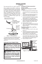
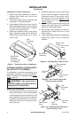
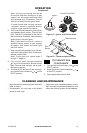
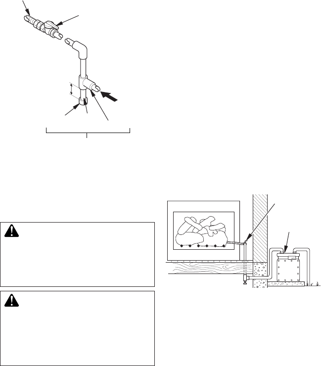
We recommend that you install a sediment
trap in supply line as shown in Figure 4.
Locate sediment trap where it is within reach
for cleaning. Install in piping system between
fuel supply and heater. Locate sediment
trap where trapped matter is not likely to
freeze. A sediment trap traps moisture and
contaminants. This keeps them from going
into log set controls. If sediment trap is not
installed or is installed wrong, log set may
not run properly.
INSTALLATION
Continued
Figure 4 - Gas Connection
* Purchase the optional CSA design-certied
equipment shutoff valve from your dealer.
** Minimum inlet pressure for purpose of input
adjustment.
3" Minimum
Sediment Trap
From Gas
Meter (5"
W.C.** to
10.5" W.C.
Pressure)
CSA Design-
Certied Equipment
Shutoff Valve With
1/8" NPT Tap*
Approved Flexible Gas Hose
(if allowed by local codes)
Tee
Joint
Pipe
Nipple
Cap
CHECKING GAS CONNECTIONS
WARNING: Test all gas piping
installing or servicing. Correct
WARNING: Never use an
-
PRESSURE TESTING GAS SUPPLY
PIPING SYSTEM
1. Disconnect log set and its individual equip-
ment shutoff valve from gas supply piping
system.
2. Cap off open end of gas pipe where equip-
ment shutoff valve was connected.
3. Pressurize supply piping system by either
using compressed air or opening main gas
valve located on or near gas meter.
4. Check all joints of gas supply piping system.
Apply noncorrosive leak detection uid to
gas joints. Bubbles forming show a leak.
5. Correct all leaks at once.
6. Reconnect log set and equipment shutoff
valve to gas supply. Check reconnected
ttings for leaks.
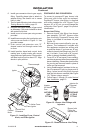
Test Pressures Equal To or Less Than
1. Close equipment shutoff valve (see
Figure 5).
2. Pressurize supply piping system by either
using compressed air or opening main gas
valve located on or near gas meter.
3. Check all joints from gas meter to equip-
ment shutoff valve (see Figure 5). Apply
noncorrosive leak detection uid to gas
joints. Bubbles forming show a leak.
4. Correct all leaks at once.
Figure 5 - Checking Gas Joints
Gas Meter
Equipment
Shutoff
Valve