


www.desatech.com
124183-01B 11
6. Install gas connector tube to gas supply
tting. Carefully shape tube to attach to
adapter tting. Be careful not to cause
kinks in tube.
7. Test for leaks following instructions under
Testing Burner for Leaks, page 12.
8. Retighten and adjust location of gas control
as necessary. Gas control should be level,
with control rod to front.
9. Install cover to burner pan using screws
provided.
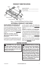
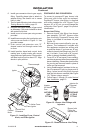
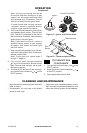
10. Install thermocouple, pilot, and ignitor onto
valve cover as shown in Figure 11. Use
provided screws.
11. Push control rod extension onto “D”
shaped control rod through center hole
in cover.
12. Install position decal and control knob
making sure to align marks with correct
stop positions of gas control. Pilot position
will allow knob to push in about 1/2". Align
decals in pilot position.
INSTALLATION
Continued
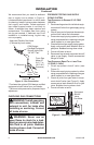
Figure 11 - Installing Cover, Control
Knob, and Piezo Ignitor
Piezo Ignitor
Control Rod
Extension
Screw
Valve Cover
Control
Knob
Thermocouple
Ignitor
Pilot
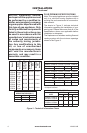
PROPANE/LP GAS CONVERSION
To convert to propane/LP gas, burner inlet
fitting and pilot orifice must be replaced.
Propane/LP burner inlet tting is supplied
with orice installed for a 24" log set. If you
have an 18" or 30" set, you must change this
orice also. See Figure 1, page 5 for product
identication.
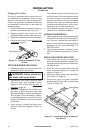
Burner Inlet Fitting
1. Remove burner inlet tting from burner
pan assembly. DO NOT remove orice
from this tting. Propane/LP burner inlet
tting is included in hardware kit (see
Figure 12).
2. Be sure to use correct orice for your ap-
pliance. The hardware kit included with
this appliance contains two orices with
a cone-like shape. If you have an 18" set,
orice for burner inlet tting is red; for a 30"
set, it is black. If you have a 24" log set,
orice is already installed inside tting.
3. For an 18" or 30" set, use a 10 mm socket or
nut driver to remove orice from propane/LP
burner inlet tting. Choose the correct orice
for your log set size and install in place of
orice you just removed.
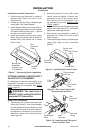
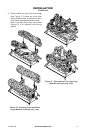
4. Using thread sealant (resistant to the ac-
tion of propane/LP gas) on larger end of
tting, screw burner inlet tting through
hole and into burner manifold (see Figure
13). Tighten using a wrench.
5 . Follow steps 1 through 12 under Natural
Gas Installation, page 10.
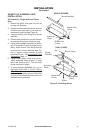
Figure 12 - Burner Inlet Fittings with
Injectors
Figure 13 - Remove Burner Inlet Fitting
Burner Inlet
Fitting for
Natural Gas
NATURAL
GAS
FITTING
PROPANE/
LP GAS
FITTING
Injector
for Natural
Gas
Injector for
Propane/
LP Gas