


www.desatech.com
124183-01B6
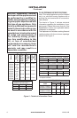
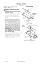
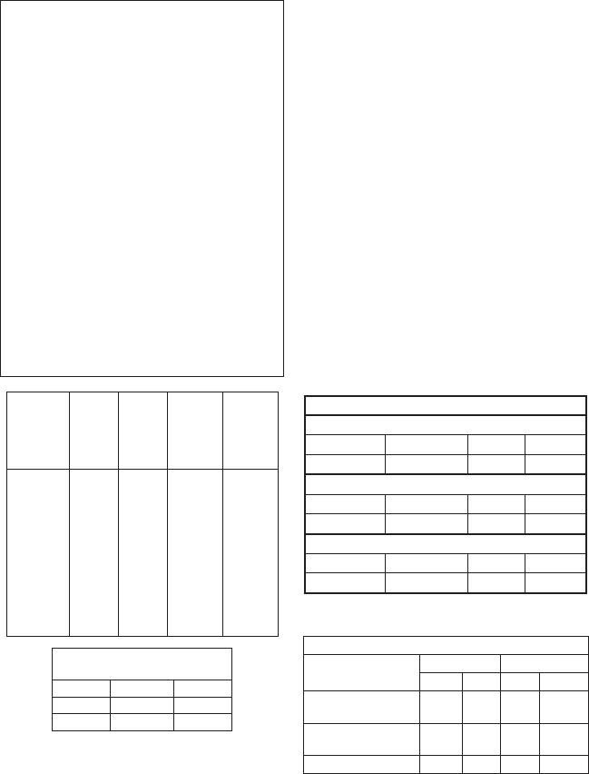
BURNER ORIFICE
LOG NATURAL PROPANE/LP
SIZE IN. NUM. IN. NUM.
VVSR18, FVSR18,
VVDR18, FVDR18
0.120 31 0.073 49
VVSR24, FVSR24
VVDR24, FVDR24
0.129 30 0.086 44
VVDR30, FVDR30 0.1405 28 0.089 43
Model
Burner
Description
Btu/Hr Input
Natural Gas
Btu/Hr Input
Propane/LP
Gas
Vent
Opening
VVSR18
FVSR18
18"
Single
50,000 40,000 8" dia.
VVSR24
FVSR24
24"
Single
60,000 50,000 8" dia.
VVDR18
FVDR18
18"
Dual
55,000 45,000 8" dia.
VVDR24
FVDR24
24"
Dual
65,000 55,000 8" dia.
VVDR30
FVDR30
30"
Dual
70,000 60,000 8" dia.
*Add 6" if safety valve/pilot is used
**At depth indicated
FUEL INLET PRESSURE
Min. Max.
NG 5.5" 10.5"
LP 11" 13"
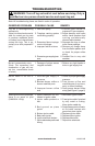
Figure 2 - Technical Information Charts
MINIMUM FIREBOX SIZES
Models: VVSR18, FVSR18, VVDR18, FVDR18
Front Width* Back Width** Depth Height
28" 16" 14" 18"
Models: VVSR24, FVSR24, VVDR24, FVDR24
Front Width* Back Width** Depth Height
29
3
/
4
" 17" 15
1
/
2
" 18"
Models: VVDR30, FVDR30
Front Width* Back Width** Depth Height
36" 27" 18" 18"
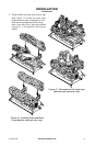
INSTALLATION
Continued
-
this type of gas appliance. Only
-
hazardous condition.
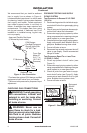
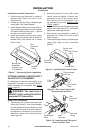
FLUE OPENING SPECIFICATIONS
Note: This vented appliance must be installed
only in a solid-fuel burning replace with a
working ue and constructed of noncombus-
tible material.
The charts in Figure 2, indicate technical
information regarding the installation of your
gas log set. Please make sure that all of the
specications shown are applicable before
installation is attempted.
The replace must include a working ue and
venting system with the minimum openings
shown in the Figure 2.