


www.desatech.com
124183-01B 7
CHECK GAS TYPE
Use only natural gas. If your gas supply is not
natural gas, you must install ON/OFF Safety
Valve/Pilot Kit (see Accessories, page 24).
Call dealer where you bought log set.
If the replace does not have a gas supply
shutoff valve, one must be installed.
VENTING SPECIFICATIONS FOR
INSTALLATION
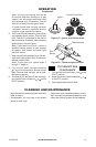
The replace chimney ue and vent must be
drafting properly. To check the vent for proper
drafting: Light a tightly rolled newspaper on
one end and place it at the inside front edge
of the replace. Observe the smoke and be
sure the vent is properly drawing it up the
chimney. If the smoke spills out into the room,
extinguish the ame and remove any obstruc-
tion until proper venting is achieved.
The chimney ue must remain open a mini-
mum of 3" at all times during the operation
of this log set.
For Massachusetts Residents Only
Installation of this vented gas log set in the
Commonwealth of Massachusetts requires
the damper be permanently removed or
welded in the fully open position.
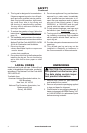
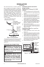
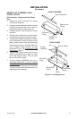
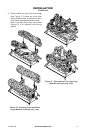
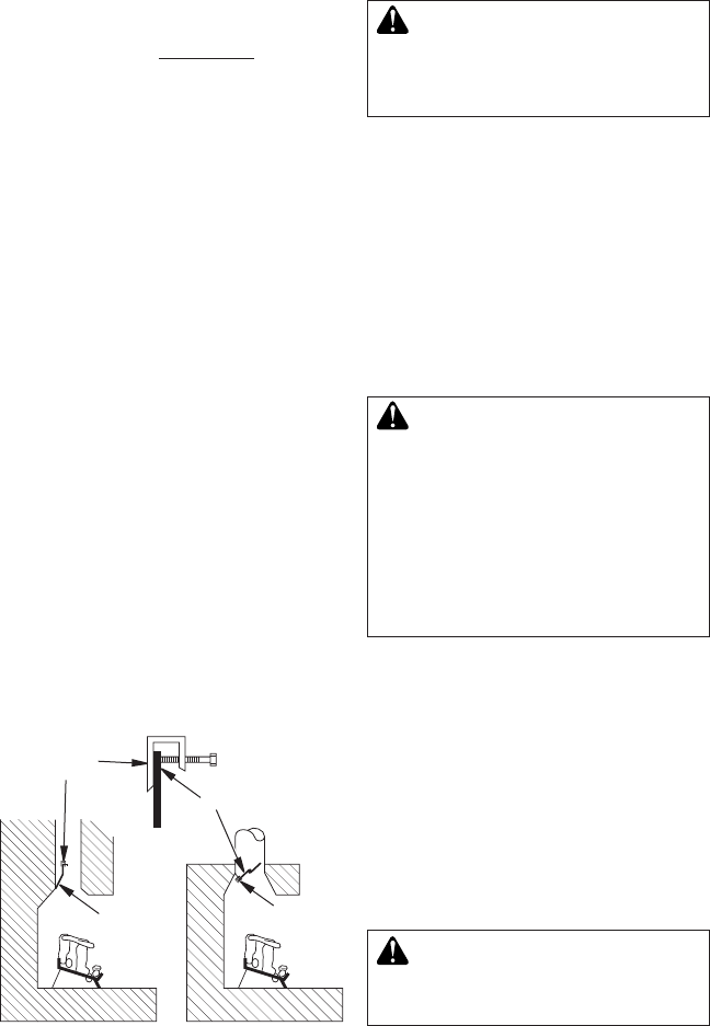
INSTALLING DAMPER CLAMP
Secure the damper stop clamp provided to
the leading edge of the damper as shown in
Figure 3. If for any reason this clamp doesn't
work on your replace, another suitable clamp
or permanent stop must be installed, or the
damper blade must be cut or removed.
INSTALLATION
Continued
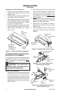
Damper
Clamp
Damper
Clamp
Damper
Manufactured
Fireplace
Masonry Fireplace
Figure 3 - Attaching Damper Clamp
Damper
CONNECTING TO GAS SUPPLY
-
local codes.
Before installing log set, make sure you have
the items listed below.
• piping (check local codes)
• sealant (resistant to Propane/LP gas)
• equipment shutoff valve
• test gauge connection
• adjustable (crescent) wrench or pliers
• sediment trap
• tee joint
• pipe wrench
-
your local codes. Use pipe of
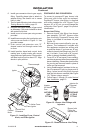
Installation must include a equipment shutoff
valve, union, and plugged 1/8" NPT tap. Lo-
cate NPT tap within reach for test gauge hook
up. NPT tap must be upstream from log set
(see Figure 4, page 8).
IMPORTANT: Install equipment shutoff valve
in an accessible location. The equipment
shutoff valve is for turning on or shutting off
the gas to the appliance.
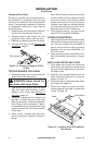
Apply pipe joint sealant lightly to male NPT
threads. This will prevent excess sealant from
going into pipe. Excess sealant in pipe could
result in a clogged burner injector.
sealant that is resistant to liquid