


www.desatech.com
124183-01B12
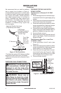
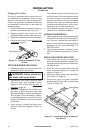
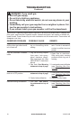
The pilot is provided with a natural gas ori-
ce installed. For propane/LP gas you must
remove it and replace it with an propane/LP
orice. The accessory hardware kit contains
an propane/LP orice with a red stripe for
converting pilot.
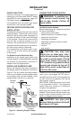
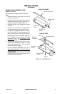
1. Gently loosen and remove pilot line con-
nection from bracket (see Figure 14).
2. Replace injector (see Figure 14) with
propane/LP pilot injector with red stripe.
3. Replace and tighten pilot line to bracket.
4. Continue with step 3 under Natural Gas
Installation, page 10.
INSTALLATION
Continued
Figure 14 - Installing Propane/LP Pilot
Orice
Pilot Injector
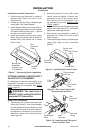
TESTING BURNER FOR LEAKS
1. Generously apply noncorrosive leak de-
tection uid to all connections.
2. Light burner with shutoff valve no more
than half open and holding a match
slightly in front of pan (see Lighting In-
structions, page 14).
3. Inspect all connections for bubbles, raw
gas odor, or ame from any area other
than burner (leaks). If leaks are detected,
shut off gas valve immediately. Tighten,
or reassemble loose connection(s) using
pipe joint compound until burner system
is leak free.
4. When burner is tested and leak free,
observe individual tongues of ame on
burner.
Note: Burner design includes more ports
on the outside of the bar. Make sure that
all ports are clear and producing ame
evenly across burner. If any ports appear
blocked, clear them by removing burner
manifold and reaming ports with a modi-
ed paper clip or other suitable tool.
5. When nished testing, turn gas shutoff
valve OFF to extinguish all ames.
ADDING PAN MATERIAL
1. Open bag of ash bed material (vermiculite)
and spread it evenly across burner pan to
top. You may overow front and sides of
pan to cover entire pan and connecting
hardware. Do not cover GA9050A-1 or
GA9150A valve.
2. Open glowing embers and evenly cover
ash bed material (vermiculite) in burner
pan.
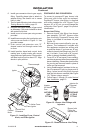
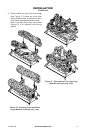
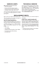
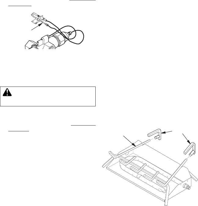
INSTALLING GRATE AND LOGS
1. Place grate over burner pan where two
outer horizontal supports on grate t into
two pan positioning notches in rear verti-
cal edge of pan.
2. Slide two rear log grate steps over two
outer horizontal supports on grate as
shown in Figure 15.
3. Place back log on grate onto grate steps
(see Figure 16, page 13).
4. Place front log(s) on grate and slide
forward against front bars on grate (see
Figure 16, page 13).
Figure 15 - Installing Grate (Pan Material
Not Shown)
Grate
Grate Steps