


www.desatech.com
116646-01E 29
Safety Features
When away from home for an extended period
of time or as a child safety feature to prevent
accidental ignition of the replace, the receiver
ON/OFF/REMOTE switch should be in the
OFF position.
Auto Shutoff Feature
1. If the average room temperature exceeds
82 degrees Fahrenheit (28 degrees Centi-
grade), the hand-held remote control will
perform a safety override and shut the
replace off. This feature is not available
in the MANU mode.
2. The receiver continuously receives signals
from the hand-held remote to control the
room temperature. If the hand-held remote
is misplaced, obstructed or for any reason
cannot transmit to the receiver, the receiver
will shut off the replace after 8 minutes.
Key Pad Lock Feature
This feature allows the user to lock/unlock the
keypad on the hand-held remote in the MANU or
AUTO mode to prevent inadvertent operation (i.e.
children operating the hand-held remote control,
etc.). The keypad is locked in either on or off. Press
the POWER and LOCK buttons together to turn
the unit on or off.
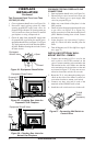
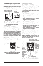
OPERATING OPTIONAL
GWMT1 WALL MOUNTED
THERMOSTAT
WARNING: Do not con-
nect the thermostat to a power
source. Electrical shock and/or
a re hazard will occur.
Light the replace as instructed in Lighting
Instructions on page 27. Set wall thermostat to
desired temperature.
This thermostat has been electronically cali-
brated at the factory and requires no adjust-
ment or leveling.
Upon installation, the thermostat must be al-
lowed to stabilize at room temperature for a
minimum of 30 minutes for proper operation.
To turn the replace off, adjust thermostat to
the lowest setting and turn the gas control knob
back to PILOT. The pilot will remain lit.
IMPORTANT: To turn the pilot off, turn the gas
control knob on the heater to the OFF position.
OPERATING FIREPLACE
Continued
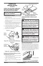
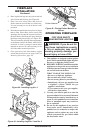
OPERATING OPTIONAL
BLOWER ACCESSORY
Locate the blower controls by opening the lower
louver panel on the replace. Blower controls
are located on the right side of the switch
bracket to the left just inside the louver panel.
The BK manual blower and the BKT thermo-
statically-controlled blower have an ON setting
and an OFF setting. The blower will only run
when the switch is in the ON position. In the
OFF position, the blower will not operate.
Note for BKT Only: If you are using BKT
blower with optional thermostat (wall mounted
or remote control) for the replace, your re-
place and blower will not turn on and off at the
same time. The replace may run for several
minutes before the blower turns on. After the
heater modulates to the pilot position, the blow-
er will continue to run. The blower will shut off
after the rebox temperature decreases.
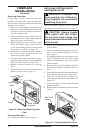
The blower helps distribute heated air from
the replace. Periodically check the louvers of
the rebox and remove any dust, dirt or other
obstructions that will hinder the ow of air.
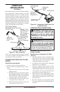
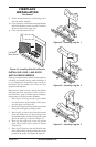
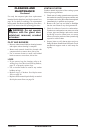
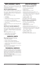
Thermocouple
Thermopile
1/8"
Pilot
Burner
Piezo
Ignitor
Figure 55 - Pilot Assembly
3/8" to 1/2"
INSPECTING BURNERS
Check pilot ame pattern and burner ame pat-
terns often.
PILOT ASSEMBLY
The pilot assembly is factory preset for the proper
ame height. Alterations may have occurred dur-
ing shipping and handling. Call a qualied service
person to readjust the pilot if necessary.
The height of the thermopile must be 3/8" to 1/2"
above the pilot ame as shown in Figure 54. The
thermocouple must be at a height of about 1/8"
above the pilot ame. The ame from the pilot
burner must extend beyond both the thermocouple
and thermopile.