


www.desatech.com
113110-01H14
-
-
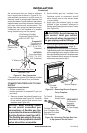
Note: If you are using a mantel with your re-
place, use the following instructions. If your
replace is built-in, see For Built-In Installa-
tion, page 16.
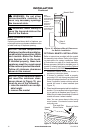
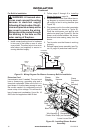
1. Install snap bushings found in hardware
kit into both holes in rear of valve cover
shield.
2. Make sure the wire harness is firmly
connected to the terminals on the blower
bracket assembly.
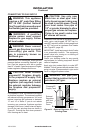
3. Note the wire locations on back of AUTO/
OFF/ON switch. The terminals on back of
switch are numbered 1, 2, and 3. Care-
fully remove red wire from terminal 3 and
blue wire from terminal 1. Black wire can
remain on middle terminal 2 (see Figure
16, page 15).
4. Carefully disconnect green and white
wires at their insulated connectors (see
Figure 17, page 15).
5. In top of the replace cabinet, locate the
four mounting holes on the outer casing.
Align these four holes with those on the
blower bracket assembly. Attach blower
bracket assembly to the outer casing with
4 #10 screws provided (see Figure 16,
page 15).
6. Route the wire harness through the hole in
left side of bafe. Pull wire harness through
lower opening on the side of the valve
cover shield (see Figure 16, page 15).
7. Insert the 4 wire harnesses into one of the
round holes in the rear of the valve cover
shield and through the rectangular hole in the
front of shield (see Figure 16, page 15).
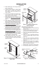
8. Reconnect red wire to switch position 3.
Reconnect blue wire to switch position 1.
Reconnect green and white wires.
9. Install the switch plate on the valve cover
shield with 2 #10 screws provided (see Fig-
ure 18, page 15). Route power cord out of
the cabinet by inserting it through the bush-
ing on the outer casing (see Figure 16, page
15). Plug fan kit into 120-Volt grounded
power supply and test operation.
Note: When switch is in the AUTO posi-
tion, the fan will start after the replace
has run for a few moments. The fan will
continue to run for several moments after
the replace has been turned off. When
switch is in the ON position, the fan will run
until turned to OFF. Reinstall upper louver
assembly (see Figure 15) and branch
support. Close lower louver door.
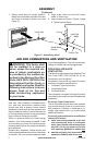
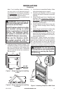
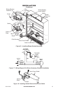
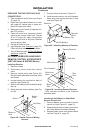
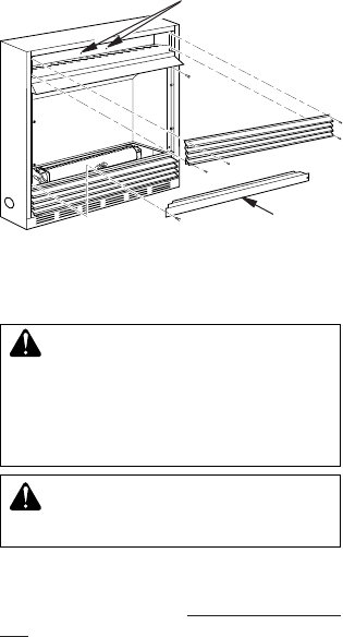
To install the blower accessory, you must rst
remove the upper louver assembly.
1. Lift screen off replace and remove log
set if installed.
2. Remove 2 screws from each side of
branch support and pull branch support
out (see Figure 15).
3. Remove 4 screws from upper louver
assembly (see Figure 15). Save these
screws.
4. Pull upper louver assembly straight out
from the cabinet. Be careful not to scratch
the paint. Set louver assembly and screws
aside.
5. Open lower louver door by swinging door
down (see Figure 15).
Blower Bracket
Mounting Holes
Branch
Support
Figure 15 - Removing Top Louver and
Branch Support
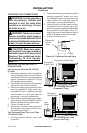
INSTALLATION
Continued