


www.desatech.com
113110-01H 13
INSTALLATION
Continued
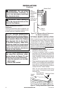
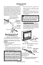
4. Route exible gas line through access
hole in hearth base.
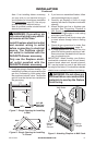
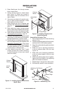
5. Center cabinet mantel on hearth base
(see Figure 12). Make sure mantel is
ush against wall and centered left to
right on base.
6. Use screws provided with mantel acces-
sory to attach mantel assembly to base
(see mantel instruction sheet).
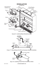
7. Attach exible gas line to replace gas
regulator. See Connecting to Gas Supply,
page 17.
8. Route electrical cord(s) through access
holes in either side of replace with bushing.
Plug electrical cord(s) into electrical outlet.
9. Check all gas connections for leaks. See
Checking Gas Connections, page 19.
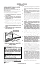
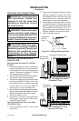
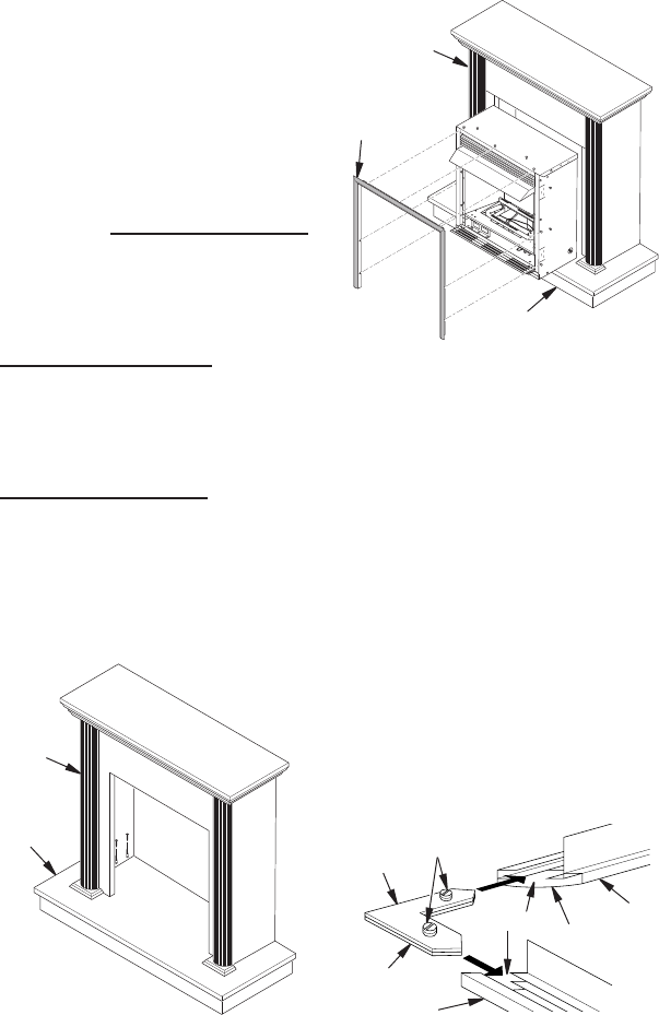
10. Carefully insert replace into cabinet mantel
(see Figure 13). Be careful not to scratch or
damage hearth base or cabinet mantel.
11. Place metal trim on shoulder screws locat-
ed on the side and top of the replace (see
Assembling Perimeter Trim). Firmly snap
trim over shoulder screws. Align replace
in mantel assembly so the trim overlaps
mantel evenly on all three sides.
12.
Lower bottom louver door. Use 3" wood
screws provided with mantel accessory
to attach replace to base (see mantel
instruction sheet).
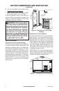
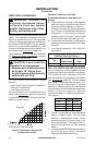
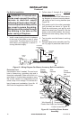
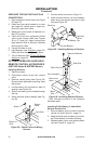
Figure 14 - Assembling Trim
Side Trim
Top
Trim
Mitered Edge
Shim
Set Screws
Adjusting
Plate
Slot
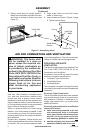
Figure 12 - Installing Cabinet Mantel onto
Hearth Base
Cabinet
Mantel
Hearth
Base
Figure 13 - Installing Fireplace into
Mantel Assembly
Cabinet
Mantel
Assembled
Trim
Hearth Base
1. Remove packaging from three remaining
pieces of trim.
2. Locate two adjusting plates with set screws,
and two shims in the hardware packet.
3. Align shim under adjusting plate as shown
in Figure 14.
4. Slide one end of adjusting plate/shim
in slot on mitered edge of top trim (see
Figure 14).
5. Slide other end of adjusting plate/shim
in slot on mitered edge of side trim (see
Figure 14).
6. While rmly holding edges of trim together,
tighten both set screws on the adjusting
plate with slotted screwdriver.
7. Repeat steps 1 through 6 for other corner.
8. Set assembly aside for later installation.