


www.desatech.com
113110-01H10
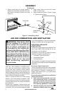
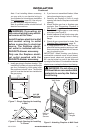
WARNING: Maintain the
minimum clearances shown
If your replace is to be used with an optional
mantel, the installation instructions included
with your mantel shows an CSA approved
method of attaching the replace/mantel sys-
tem to a wall. IMPORTANT: Only use optional
cabinet or corner mantels specied in this
manual. Purchase the optional mantel from
your dealer (see Accessories, page 35).
If your replace is to be recessed into the wall,
see Built-In Fireplace Installation to secure
your replace into the wall.
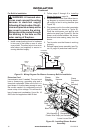
CAUTION: If you install the
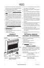
For convenience and efficiency, install
replace
• where there is easy access for operation,
inspection, and service
• in coldest part of room
An optional blower kit is available from your
dealer. See Accessories, page 35. If planning
to use blower, follow instructions provided with
blower for power source.
INSTALLATION
Continued
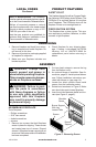
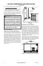
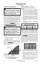
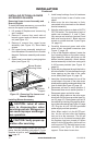
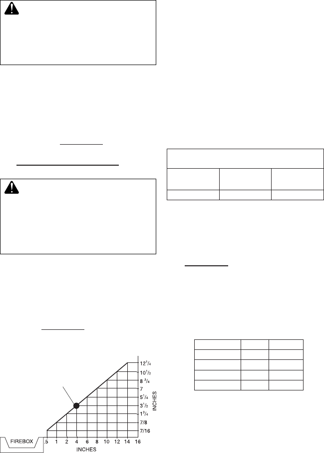
Minimum Clearances For Side
A. Clearances from the side of the replace
cabinet to any combustible material and
wall should follow diagram in Figure 6.
Example: The face of a mantel, bookshelf,
etc. is made of combustible material and
protrudes 3
1
/
2
" from the wall. This com-
bustible material must be 4" from the side
of the replace opening (see Figure 6).
B. Clearances from the top of the replace
opening to the ceiling should not be less
than 36".
C.
For mantel clearances, see Figure 10
on page 12.
Figure 6 - Minimum Clearance for
Combustible to Wall
*Minimum 16" from Side Wall
Example
*
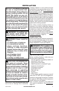
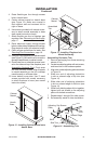
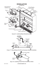
Built-in installation of this replace involves
installing replace into a framed-in enclosure.
This makes the front of replace ush with
wall. An optional trim kit accessory is available
(see Accessories, page 35). Trim will extend
past sides of replace approximately 1/2".
This will cover the rough edges of the wall
opening. If installing a built-in mantel above
the replace, you must follow the clearances
shown in Figure 10, page 12. Follow the
instructions below to install the replace in
this manner.
1. Frame in rough opening. Use dimensions
shown in Figure 7, page 11 for the rough
opening. If installing in a corner, use di-
mensions shown in Figure 8, page 11 for
the rough opening. The height is 26
7
/8"
which is the same as the wall opening
above.
2. If installing GA3450TA blower accessory,
do so at this time. Follow instructions
included with blower accessory.
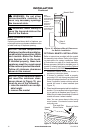
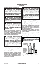
MINIMUM CLEARANCE TO
COMBUSTIBLE MATERIALS
Left and
Bottom and
Rear
36" 6" 0"
Actual Framing
Height 26" 26
7
/8"
Front Width 26
3
/4" 26
7
/8"
Depth 9
1
/2" 10
1
/2"
Bottom 3/4" 3/4"