


www.desatech.com
113110-01H20
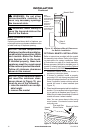
CONNECTIONS
1.
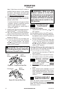
Open equipment shutoff valve (see Figure
25, page 19).
2. Open main gas valve located on or near
gas meter for natural gas or open pro-
pane/LP supply tank valve.
3. Make sure control knob of replace is in
the OFF position.
4. Check all joints from equipment shutoff
valve to gas control valve (see Figures
26 or 27, page 19). Apply noncorrosive
leak detection uid to all joints. Bubbles
forming show a leak.
5. Correct all leaks at once.
6. Light replace (see Operation, page 23).
Check all other internal joints for leaks.
7. Turn off replace (see To Turn Off Gas to
Appliance, page 24).
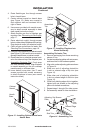
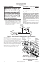
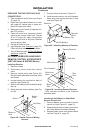
REMOTE CONTROL ACCESSORIES
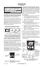
1. Remove screws.
2. Disconnect switch wires from control
valve.
3. Remove switch plate (see Figure 28).
Discard switch plate after removing. Save
the screws.
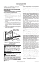
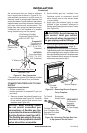
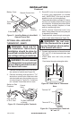
4. Locate battery clip mounted on back of
receiver (see Figure 29).
5. Slide 9-volt battery (not included) through
the clip.
6. Attach terminal wires to battery (see Fig-
ure 29).
INSTALLATION
Continued
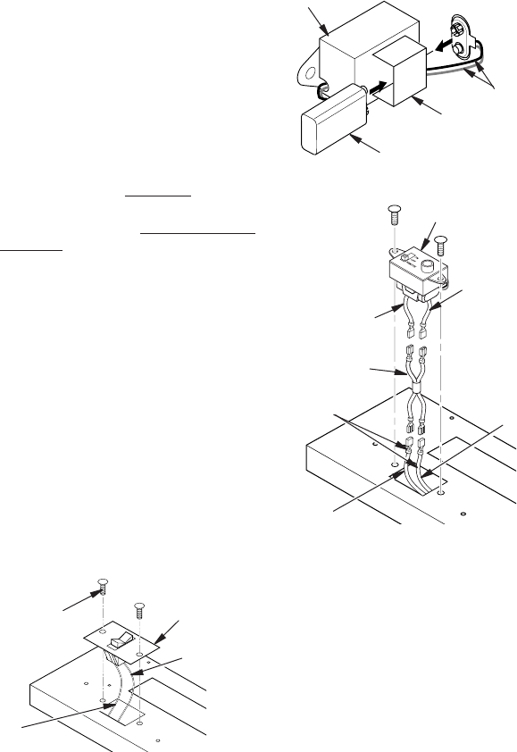
Figure 28 - Switch Plate and Wiring
Harness
Figure 29 - Attaching Battery to Receiver
Receiver
Screw
Switch
Plate
Black
Wire
Red Wire
Battery Clip
9-Volt Battery
Terminal
Wires
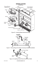
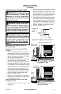
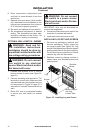
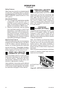
Figure 30 - Installing Remote Receiver
* Wire harness provided in the fireplace
hardware pack.
Wires from
Valve
Wire Harness*
Black
Wire
Red
Wire
Red Wire
Black Wire
Remote Receiver
7. Connect wires as shown in Figure 31.
8. Install remote receiver unit onto replace
base using two screws removed in step
one (see Figure 30).
Remote Control Unit
1. Remove battery cover on back of remote
control unit (see Figure 31, page 21).
2. Attach terminal wires to battery (not includ-
ed). Place battery into battery housing.
3.
Replace battery cover onto remote control
unit
(see Figure 31, page 21)
.