


www.desatech.com
113195-01B 13
INSTALLATION
Continued
CAUTION: Use only new,
black iron or steel pipe. Inter
-
nally-tinned copper tubing may
be used in certain areas. Check
your local codes. Use pipe of
1/2" diameter or greater to allow
proper gas volume to fireplace
insert. If pipe is too small, undue
loss of volume will occur.
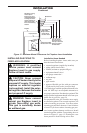
Installation must include an equipment shutoff
valve and plugged 1/8" NPT tap. Locate NPT
tap within reach for test gauge hook up. NPT
tap must be upstream from fireplace insert (see
Figure 14).
IMPORTANT: Install equipment shutoff valve
in an accessible location. The equipment shutoff
valve is for turning on or shutting off the gas to
the appliance.
Check your building codes for any special re
-
quirements for locating equipment shutoff valve
to fireplaces.
Apply pipe joint sealant lightly to male NPT
threads. This will prevent excess sealant from
going into pipe. Excess sealant in pipe could result
in clogged fireplace valves.
WARNING: Use pipe joint
sealant that is resistant to liquid
petroleum (LP) gas.
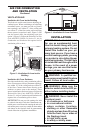
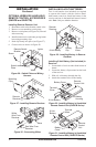
We recommend that you install a sediment trap in
supply line as shown in Figure 14. Locate sediment
trap where it is within reach for cleaning. Install
in piping system between fuel supply and heater.
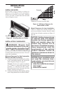
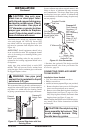
Figure 13 - External Regulator with Vent
Pointing Down
Propane/LP
Supply Tank
External
Regulator
Vent
Pointing
Down
Locate sediment trap where trapped matter is not
likely to freeze. A sediment trap traps moisture
and contaminants. This keeps them from going
into fireplace insert gas controls. If sediment trap
is not installed or is installed wrong, fireplace may
not run properly.
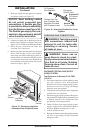
CSA Design-
Certified Equipment
Shutoff Valve With
1/8" NPT Tap*
Supplied Flexible
Gas Line
3" Minimum
Propane/LP
From External
Regulator (11"
W.C. to 14"
W.C. Pressure)
Natural
From Gas
Meter (5" W.C.
to 10.5" W.C.
Pressure)
Cap Pipe Tee
Nipple Joint
Sediment Trap
Figure 14 - Gas Connection
* Purchase the optional CSA design-certified
equipment shutoff valve from your dealer. See
Accessories, page 34.
CONNECTING FIREPLACE INSERT
TO GAS SUPPLY
Installation Items Needed
• 5/16” hex socket wrench or nut-driver
• Phillips screwdriver
•
sealant (resistant to propane/LP gas, not provided)
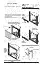
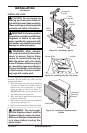
1. Remove fireplace insert screen. Lift fireplace
insert screen up and pull out to remove.
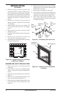
2.
Remove screws that attach log base assembly to
fireplace insert (see Figure 15, page 14). Care
-
fully lift up log base assembly and remove from
fireplace insert (see Figure 15, page 14).
Note: If adding the G8010 series brick liner acces-
sory, install it now. Follow instructions in G8010
accessory kit.
CAUTION: Do not pick up log
base assembly by burners. This
could damage burners. Only
handle base by grates.