


www.desatech.com
122663-01D 5
CAUTION: Do not expose the
heater to the elements (such as
rain, etc.)
CAUTION: Wear gloves and
safety glasses for protection
during installation and main-
tenance.
Plan where to locate and frame replace.
Before installation consider the following:
1. Fireplace location must allow for wall and
ceiling clearances (see Installation Clear-
ances).
2. Fireplace screen should not be exposed
to direct sunlight from windows or doors.
3. Unit can be wired for either 120/60 (15
amp circuit) or 240/60 (20 amp circuit).
A dedicated circuit should be provided
to avoid circuit breaker trips or blown
fuses.
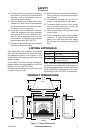
Flush Installations are recommended where
living space is limited or at a premium. Since
space required to enclose replace would
be located beyond an outside wall, this in-
stallation would require additional planning
and construction. Check local codes for any
restrictions.
Projected Installations can extend any dis-
tance into room. A projection may be ideal for
a new addition on an existing, nished wall.
Corner Installations make use of space
that may not normally be used and provides
a wider and more efcient viewing angle and
heat distribution.
Internal Wall Installations provide a discrete
option for room separation and can also be an
ideal addition to an existing wall.
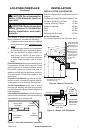
LOCATINg FIREPLACE
Continued
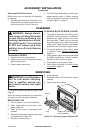
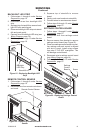
Figure 3 - Possible Installation Locations
Internal Wall
Installation
Full Projection
Installation
Flush
Installation
Corner
Installation
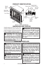
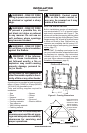
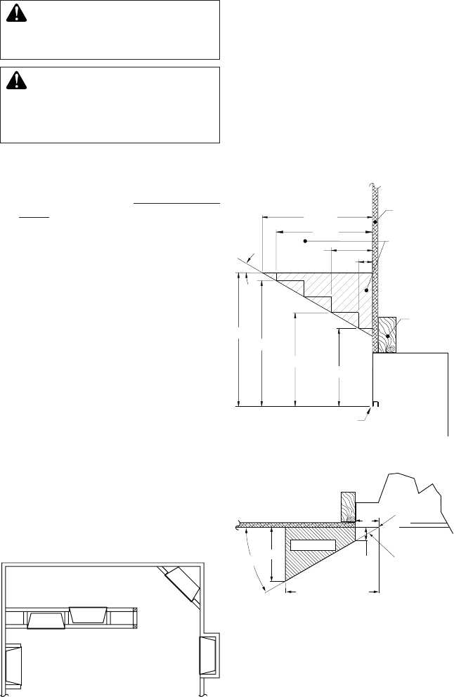
Facing Material May
Be Noncombustible
Wall Treatments or
Combustible Wood
Combustible Wood
Mantels and Trims
May Extend Above
Profile Shown when
Maintained within
30° Parameter
Shown
Framed
Material
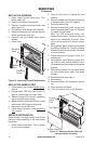
To p of Cabinet
Note: All Mantel Clearances
are Measured from Top of
Fireplace Opening
30°
23"
12" Ref.
21"
4
1
/
2
"
1
1
/
2
"
15" Min.
17"
10
1
/
2
"
Figure 4 - Mantel Clearances
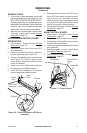
T op View of Fireplace
5"
3"
30°
1
3
/
4
" Max.
Minimum 10"
from Perpendicular
Side Wall
Edge of
Firebox
Opening
Combustible
Material Must
Not Overlap
Front Face
Safe Zone
Figure 5 - Mantel Side Clearances
INSTALLATION
INSTALLATION CLEARANCES
Minimum clearances to combustible construc-
tion are:
Top, Back and Sides of Recessed Cabinet 0" Min.
Drywall to Sides of Front Face 0" Min.
Framing at Nailing Flanges 0" Min.
Ceiling to Opening 36" Min.
Floor 0" Min.
Front 36" Min.
Perpendicular Side Wall 10" Min.
M
antel Clearances
For mantel clearances see Figures 4 and 5.