


www.desatech.com
122663-01D 11
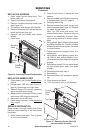
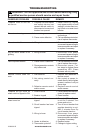
LED Drum
Assembly
Screws
White
Wire
Red
Wire
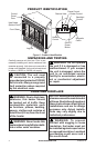
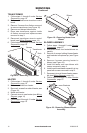
Figure 16 - Flame Generation LED Drum
Assembly
Motor
Clamps
SERVICINg
Continued
7. Reattach wires to motor and LED drum.
Note: LED drum wires are polarity sensi-
tive and must be connected correctly.
White wire plugs onto left terminal and red
wire plugs onto right terminal. Motor wires
can be connected to either terminal.
8. Follow steps 8 through 13 under Service
Preparation, page 10.
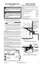
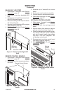
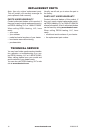
MAIN CONTROL BOARD
1. Follow steps 1 through 6 under Service
Preparation, page 10.
2. Disconnect wires to main control board.
3. Squeeze top of standoffs to remove main
control board and discard.
4. Install new control board by gently pushing
onto standoffs.
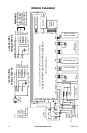
5. Reconnect wires to main control board
(see Wiring Diagram, page 14).
6. Follow steps 8 through 13 under Service
Preparation, page 10.
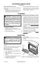
Figure 17 - Control Board
Main Control
Board
Standoffs
Transformer
SCREEN GLASS
1. In the event of glass breakage, vacuum all
remaining glass pieces with a shop vac. DO
NOT VACUUM WHILE PIECES ARE HOT.
Replace glass only with replacement part
specically for this heater. Never substitute
material. Only fully tempered soda lime
safety glass may be used on this heater.
2. Remove and replace glass, follow steps
1 through 13 (skip step 7) under Service
Preparation, page 10.
LED DRUM AND MOTOR (FLAME
GENERATION)
1. Follow steps 1 through 6 under Service
Preparation, page 10.
2. Disconnect wires from motor and LED
drum assembly.
3. Remove screws from bottom panel to
remove assembly (see Figure 16).
4. If motor on assembly fails, loosen clamps
(see Figure 16). Remove screws from
motor. Hold universal joint while removing
motor and discard.
5. Install new motor. Slide motor shaft into
universal joint and tighten clamps.
6. Hold LED drum assembly in place on
bottom panel and replace screws.