


www.desatech.com
116200-01L 9
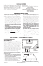
VENTING INSTALLATION
NOTICE: Failure to follow these
instructions will void the war-
ranty.
NOTICE: Do not seal termination
cap to vent pipe. Cap must be
removable for vent inspection
and maintenance.
INSTALLATION PRECAUTIONS
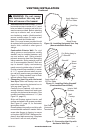
• Wear gloves and safety glasses for pro-
tection
• Use extreme caution when using ladders
or when on roof tops
• Be aware of electrical wiring locations in
walls and ceilings
The following actions will void the warranty
on your venting system:
• Installation of any damaged venting com-
ponent
• Unauthorized modication of the venting sys-
tem (Do not cut or alter vent components)
• Installation of any component part not
manufactured or approved by DESA Heat-
ing, LLC
• Installation other than as instructed by
these instructions
WARNING: This gas replace
and vent assembly must be
vented directly to the outside.
The venting system must NEVER
be attached to a chimney serv-
ing a separate solid fuel burning
appliance. Each direct-vent gas
appliance must use a separate
vent system. Do not use com-
mon vent systems.
WARNING: Vent pipe air
space clearances to combus-
tibles are 1" on all sides except
on the horizontal sections,
which require 2" clearances
from the top of the pipe. Where
the termination cap penetrates
a combustible wall, 1" air space
clearance is required.
NOTICE: Read these instruc-
tions completely before attempt-
ing installation.
These models are tested and approved for
use with DESA Heating, LLC (direct-vent) pipe
components and terminations.
The venting system must terminate on the out-
side of the structure and can not be attached
to a chimney or ue system serving a separate
solid fuel or gas burning appliance. A direct-vent
appliance must have its own venting system.
DO NOT common vent this appliance.
These models are approved to be vented
either horizontally through an outside wall or
vertically through a roof or chase enclosure
using the following guidelines:
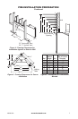
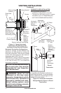
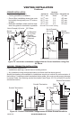
• When venting system terminates horizon-
tally on an outside wall, you may install
a standoff if the termination cap is to be
installed directly on a combustible nish
such as vinyl, wood, stucco, etc.
• Never run the vent downward as this may
cause excessive temperatures which could
cause a re.
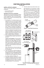
• Vent pipe air space clearances to com-
bustibles are 1" on all sides except on the
horizontal sections, which requires 2" clear-
ance from the top of the pipe. Where the
termination cap penetrates a combustible
wall, 1" air space clearance is required.
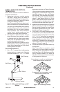
• Snorkel terminations are required when
minimum clearance to grade cannot be
met (see Figure 16 on page 13).
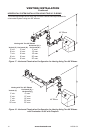
• Have replace and selected vent compo-
nents on hand to help determine the exact
measurements when elbowing or offsetting.
Always use wall restops when penetrating
walls and restops when penetrating ceil-
ings or attic spaces.
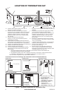
• If using a venting conguration of only
horizontal venting with no vertical run, a
1/4" rise for every 12" of run toward the
termination is required.
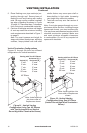
• For installation of replace at elevations of
4000 feet or greater, pay special attention
to venting requirement recommendations.
WARNING: Read all instructions
completely and thoroughly before
attempting installation. Failure to
do so could result in serious injury,
property damage or loss of life.