


www.desatech.com
116200-01L16
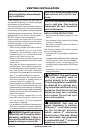
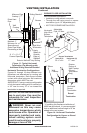
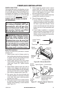
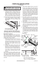
5. Place ashing over pipe section(s) ex-
tending through roof. Secure base of
ashing to roof and framing with roong
nails. Be sure roong material overlaps
top edge of ashing as shown in Figure
19, page 15. There must be a 1" clearance
from vent pipe to combustible materials.
6. Continue to add pipe sections until height
of vent cap meets the minimum building
code requirements described in Figure 7
on page 8.
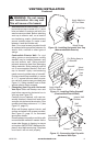
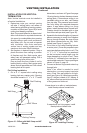
Note: You must increase vent height for
steep roof pitches. Nearby trees, adjoining
rooines, steep pitched roofs and other
VENTING INSTALLATION
Continued
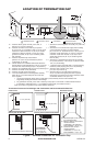
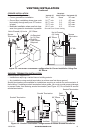
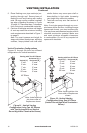
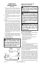
Figure 21 - Vertical Venting
Conguration Using Two 90° Elbows
with Two Horizontal Runs (Vertical
Round High Wind Termination Shown)
Note: Install restrictor
into inner collar of
replace as shown.
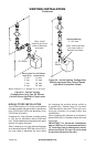
45° Elbow
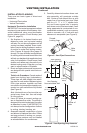
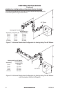
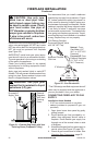
Figure 22 - Vertical Venting
Conguration Using One 90° Elbow
(Vertical Round High Wind Termination
Shown)
45° Elbow
Note: Install restrictor into
inner collar of replace as
shown.
similar factors may cause poor draft or
down-drafting in high winds. Increasing
vent height may solve this problem.
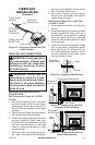
7. Twist-lock vent cap onto last section of
vent pipe.
Note: If vent pipe passes through any occu-
pied areas above rst oor, including storage
spaces and closets, you must enclose pipe.
You may frame and sheetrock enclosure with
standard construction material. Make sure
and meet minimum allowable clearances
to combustibles. Do not ll any required air
spaces with insulation.
Vertical Termination Congurations
Figures 21 through 24 show four different
congurations for vertical termination.
Venting with Two 90° Elbows
Vertical (V)
Horizontal (H
1
) +
Horizontal (H
2
)
5' min. 2' max.
6' min. 4' max.
7' min. 6' max.
8' min. 8' max.
20' max. 8' max.
Venting with One 90° Elbow
Vertical (V) Horizontal (H)
5' min. 2' max.
6' min. 4' max.
7' min. 6' max.
8' min. 8' max.
20' max. 8' max.