


www.desatech.com
116200-01L12
VENTING INSTALLATION
Continued
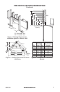
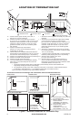
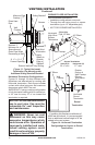
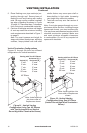
Figure 13 - Typical Horizontal
Termination Cap Mounting with
Additional Siding Standoff Installed
Siding Standoff
Screws
High Wind
Termination
Apply
Mastic to
Outside
Edge of
Standoff
Exterior Wall with Vinyl Siding
11
1
/
2
" x 11
1
/
2
"
Framed Opening
Maintain 1"
Minimum Air
Space Around
Outer Pipe When
Penetrating a Wall
Minimum Pipe
Overlap 1
1
/
4
"
Wall
Firestop
Direct-Vent
Pipe
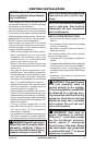
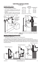
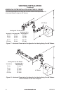
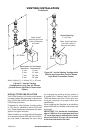
Horizontal Termination Congurations
Figures 14 through 18 show different con-
gurations and alternatives for venting with
horizontal termination. Each gure includes
a chart with critical minimum and maximum
dimensions which MUST be met.
IMPORTANT: If using a venting conguration
of only horizontal venting with no vertical run,
a 1/4" rise for every 12" of run toward the
termination is required.
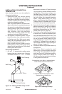
NOTICE: Do not seal termination
cap to vent pipe. Cap must be
removable for vent inspection
and maintenance.
WARNING: Never run vent
downward as this may cause
excessive temperatures which
could cause a re. Operation of
improperly installed and main-
tained venting system could
result in serious injury, property
damage or loss of life.
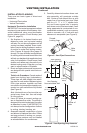
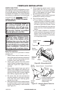
GROUND FLOOR INSTALLATION
Recommended Applications:
• Installation using cabinet surrounds
• Through the wall using round or square
termination (up to 12" adjustable pipe)
• NOT FOR CORNER INSTALLATION
Horizontal
High Wind
Square
Termination
Wall Firestop
45° Elbow
Figure 14 - Horizontal Termination
Conguration for Square or Round
Terminations
45° Elbow
Wall
Firestop
Horizontal
Round
Termination
Exterior
Portion of
Wall Firestop
(Round
Termination
Only)
Adjustable
Pipe 12" Max.
Round
Termination
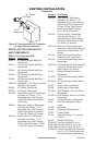
* If installing this replace at altitudes of
4000 feet and above, it is recommended
that an additional vertical height of 6" be
added to the vent system.
Square Termination
Vertical (V) Horizontal (H)
32
3
/
4
" min. 17" max.