


www.desatech.com
116200-01L 21
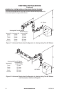
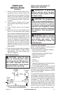
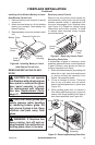
7. Check to make sure that power cord is
completely clear of blower wheel and
that there are no foreign objects in blower
wheel. Also double check all wire leads
and make sure wire routing is not pinched
or in a precarious position. Correct ac-
cordingly.
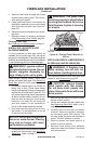
8. Turn on power to duplex outlet if previ-
ously turned off per warning in column 1,
page 19.
9. Plug in blower power cord to duplex
outlet.
10. Blower will only run when speed control
knob is in the ON position and thermal
switch senses temperature after replace
begins to heat up. Blower speed can be
adjusted by rotating control knob. To turn
off, turn knob fully counterclockwise until
it clicks off. If blower is ON and has been
running with replace operating, blower
will continue to run for a short time after
replace has been turned off. As thermal
switch cools down, blower shuts down
automatically.
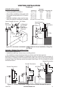
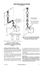
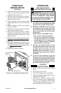
11. Peel off backing paper and stick supplied
wiring diagram decal on rebox bottom
approximately 12" in front of blower (see
Figure 28, page 20).
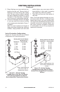
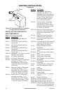
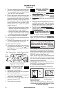
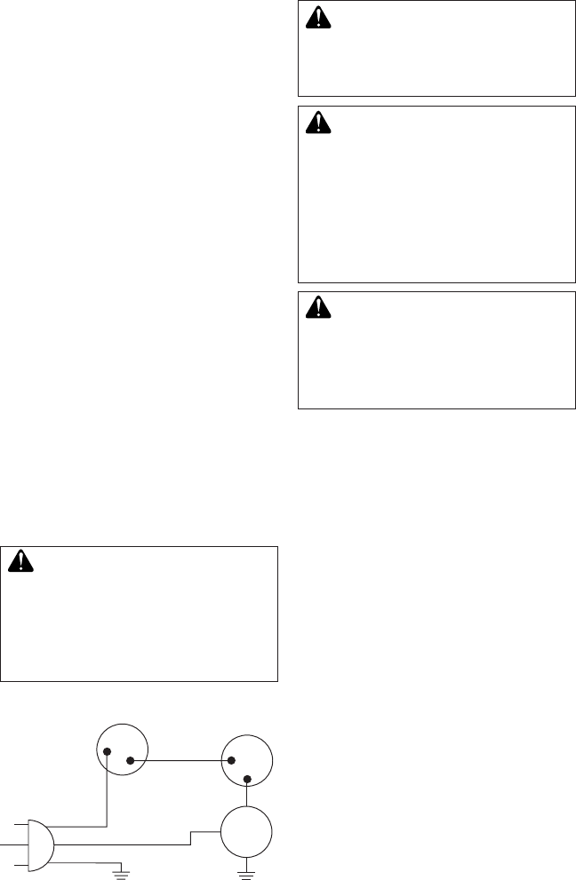
Blower Wiring Diagram
CAUTION: Label all wires
prior to disconnection when
servicing controls. Wiring errors
can cause improper and dan-
gerous operation. Verify proper
operation after servicing.
FIREPLACE
INSTALLATION
Continued
Figure 30 - Blower Wiring Diagram for
Thermostat-Controlled Models
Blue
Variable
Fan Switch
Fan Switch
(N.O.)
Green
White
On
110/115
V .A.C.
Blower
Motor
Black
Off
1
2
Black
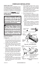
INSTALLING GAS PIPING TO
FIREPLACE LOCATION
WARNING: A qualified
service person must connect
replace to gas supply. Follow
all local codes.
CAUTION: For propane/LP
units, never connect replace di-
rectly to the propane/LP supply.
This heater requires an external
regulator (not supplied). Install
the external regulator between
the replace and propane/LP
supply.
WARNING: Never connect
natural gas replace to private
(non-utility) gas wells. This
gas is commonly known as
wellhead gas.
Installation Items Needed
Before installing replace, make sure you
have the items listed below.
• external regulator (supplied by installer)
• piping (check local codes)
• sealant (resistant to propane/LP gas)
• equipment shutoff valve *
• test gauge connection *
• sediment trap
• tee joint
• pipe wrench
• approved exible gas line with gas connec-
tor (if allowed by local codes)
* A CSA design-certied equipment shutoff
valve with 1/8" NPT tap is an acceptable al-
ternative to test gauge connection. Purchase
the CSA design-certied equipment shutoff
valve from your retailer.
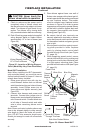
For propane/LP connection only, the installer
must supply an external regulator. The exter-
nal regulator will reduce incoming gas pres-
sure. You must reduce incoming gas pressure
to between 11" and 14" of water. If you do
not reduce incoming gas pressure, replace
regulator damage could occur. Install exter-
nal regulator with the vent pointing down as
shown in Figure 31, page 22. Pointing the vent
down protects it from freezing rain or sleet.