


www.desatech.com
116200-01L 19
FIREPLACE INSTALLATION
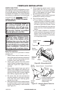
Blower Location
Side View
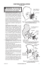
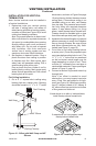
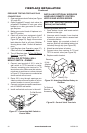
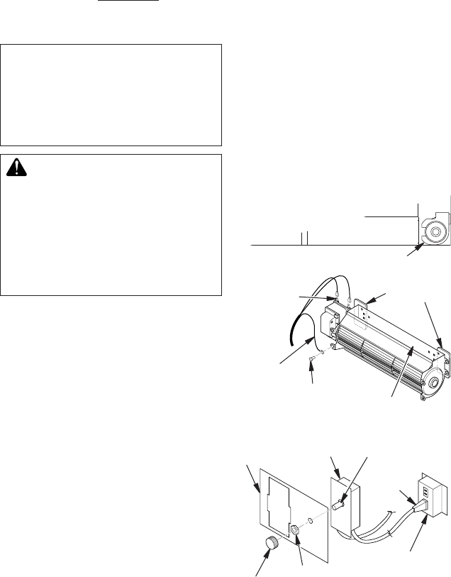
Figure 26 - Blower Model BK
Magnetic
Strips
Exhaust Port
Screw
Green
Ground
Wire
Spade
Terminals
Lower Firebox
Cavity
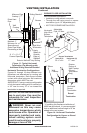
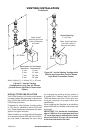
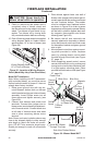
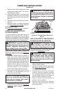
6. While supporting speed control, secure
control shaft with lock nut by pushing
and turning lock nut with pliers clockwise
until it is tight against front panel. Place
provided control knob on shaft.
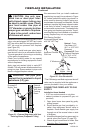
7. Turn on power to duplex outlet if previously
turned off per warning in column 1.
8. Plug in blower power cord.
a. If your rebox is installed as a free-
standing unit with an accessory mantel,
determine whether power cord will exit
left side or right side of rebox. Route
power cord through exit hole and plug
power cord into a wall receptacle near
rebox.
b. If your rebox installation is recessed
and/or pre-wired, plug power cord into
duplex outlet provided. Refer to your
rebox owner’s manual for instructions
on wiring duplex outlet.
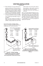
Figure 27 - Attaching Speed Control to
Firebox
Speed Control
Control Shaft
Locknut
Control
Knob
Switch
Bracket
Blower
Plug-In
Duplex Outlet (Located
beneath rebox oor
against lower right
outside wall)
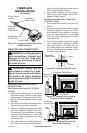
CHECK GAS TYPE
Use proper gas type for the replace unit you
are installing. If you have conicting gas types,
do not install replace. See retailer where you
purchased the replace for proper replace
according to your gas type or to purchase gas
conversion kit (see Accessories, page 42).
INSTALLING OPTIONAL BLOWER
ACCESSORIES
NOTICE: If installing blower in
an existing replace with gas
connections, shut off gas sup-
ply and disconnect heater from
gas supply. Contact a qualied
service person to do this.
WARNING: If there is a duplex
electrical outlet installed in the
right side of the bottom of the
replace base area, be sure that
the electrical power to the outlet is
turned off before proceeding with
blower installation. Failure to do
this may result in serious injury.
Model BK Installation
Follow all instructions provided in blower
accessory kit.
1. Attach power cord to blower motor by
rmly pushing two female terminals at end
of power cord onto two spade terminals
on blower motor (see Figure 26).
2. Attach green ground wire from power
cord to blower housing using screw pro-
vided (see Figure 26). Tighten screws
securely.
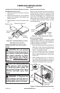
3. Place blower against lower rear wall of
rebox outer wrapper with exhaust port
directed upward. Blower will t inside back
opening and be held in position against
back wall by magnets (see Figure 26).
4. Be certain that all wire terminals are
securely attached to terminals on blower
motor and that screw retaining green
ground wire is tight.
5. Mount speed control box to switch bracket
by placing plastic control shaft forward
through round opening in switch bracket
(see Figure 27).