


www.desatech.com
7901053-01J
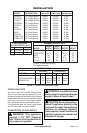
INSTALLATION
Continued
Convert the gas control valve by changing out
the valve regulator portion of the gas valve.
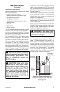
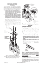
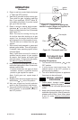
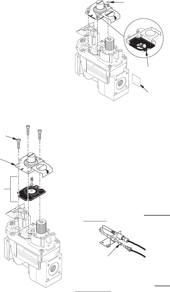
1.
Using a TORX T20 or slotted screwdriver, re-
move and discard the three mounting screws,
pressure regulator tower and diaphragm/
spring components (see Figure 13).
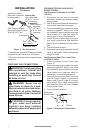
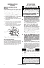
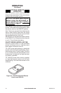
2. Insure that the rubber gasket is properly
positioned on the new pressure regulator
assembly. Install the new pressure regu-
lator assembly to the valve using the new
mounting screws supplied with the kit.
Tighten screws securely (approximately
25 in-lbs.) See Figure 14.
3. Install the identication label enclosed
with the gas valve regulator to the valve
body where it can easily be seen (see
Figure 14).
Figure 13 - Removing Mounting
Screws, Pressure Regulator Tower and
Diaphragm/Spring Components
O
F
F
P
I
L
O
T
O
N
Mounting
Screws
Pressure
Regulator
Tower
Diaphragm/
Spring
Components
Figure 14 - Installing Pressure Regulator
Assembly
O
F
F
P
I
L
O
T
O
N
Mounting
Screws
Rubber
Gasket
Identication
Label
Figure 15 - Installing Propane/LP Pilot Orice
O
F
F
P
I
L
O
T
O
N
Pilot
Injector
The pilot is provided with a natural gas ori-
ce installed. For propane/LP gas you must
remove it and replace it with an propane/LP
orice. The hardware kit contains an propane/
LP orice with a red stripe for converting the
pilot.
1. Gently loosen and remove the pilot line con-
nection from the bracket (see Figure 15).
2. Replace the injector (see Figure 15) with
the propane/LP pilot injector with the red
stripe.
3. Replace and tighten the pilot line to the
bracket.
4. Continue with step 6 under Natural Gas
Installation, page 5.
Note: Follow the instructions in your hearth
kit owner’s manual under the section, Testing
Burner for Leaks.
If pilot ow is weak adjustments can be made
with the pilot adjustment screw. The screw is
located below the wire harness on gas valve
body (see Figure 14).