


www.desatech.com
901053-01J4
INSTALLATION
Continued
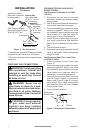
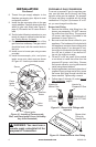
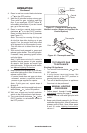
Figure 4 - Equipment Shutoff Valve
Open
Closed
Equipment
Shutoff Valve
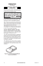
CHECKING GAS CONNECTIONS
and connections, internal and
WARNING: Never use an
-
PRESSURE TESTING GAS SUPPLY
PIPING SYSTEM
1. Disconnect log set and its individual
equipment shutoff valve from gas supply
piping system.
2. Cap off open end of gas pipe where equip-
ment shutoff valve was connected.
3. Pressurize supply piping system by either
opening propane/LP supply tank valve
for propane/LP gas or opening main gas
valve located on or near gas meter for
natural gas, or using compressed air.
4. Check all joints of gas supply piping sys-
tem. Apply noncorrosive leak detection
uid to all joints. Bubbles forming show a
leak.
5. Correct all leaks at once.
6. Reconnect log set and equipment shutoff
valve to gas supply. Check reconnected
ttings for leaks.
1. Close equipment shutoff valve (see
Figure 4).
2. Pressurize supply piping system by either
opening propane/LP supply tank valve
for propane/LP gas or opening main gas
valve located on or near gas meter for
natural gas, or using compressed air.
3. Check all joints from gas meter for natural
gas (see Figure 5, page 5) or propane/LP
supply (see Figure 6, page 5) to equip-
ment shutoff valve. Apply noncorrosive
leak detection uid to all joints. Bubbles
forming show a leak.
4. Correct all leaks at once.
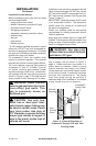
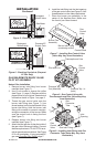
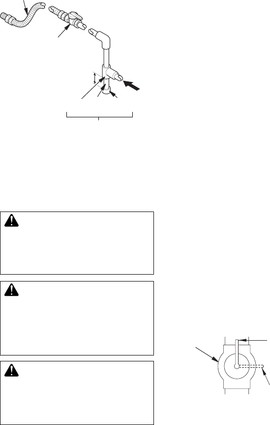
Tee Pipe Cap
Joint Nipple
Approved Flexible
Gas Hose (if allowed
by local codes)
Figure 3 - Gas Connection
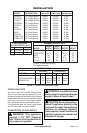
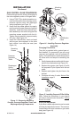
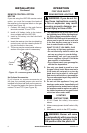
* Purchase the optional CSA design-certied
equipment shutoff valve from your dealer.
** Minimum inlet pressure for purpose of input
adjustment.
3" Minimum
Sediment Trap
CSA Design-Certied
Equipment Shutoff Valve
With 1/8" NPT Tap*
Natural Gas
From Gas Meter
(5" W.C.** to 10.5"
W.C. Pressure)
From External
Regulator
(11" W.C.**
to 14" W.C.
Pressure)