


www.desatech.com
5901053-01J
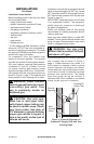
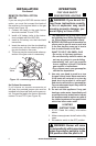
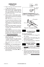
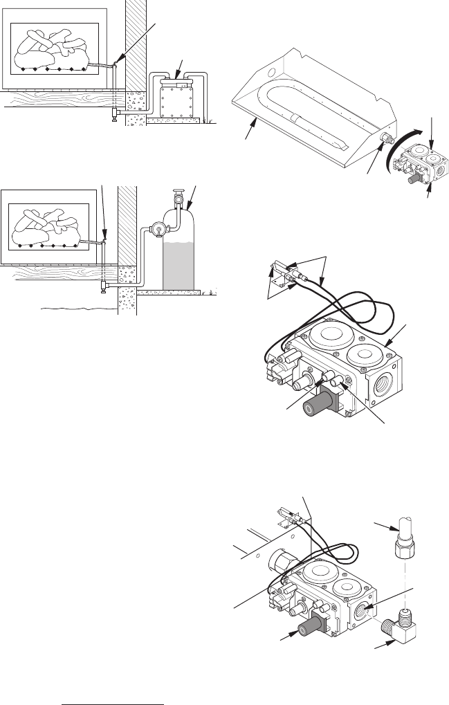
Figure 6 - Checking Gas Joints (Propane/
LP Gas Only)
Figure 5 - Checking Gas Joints
Gas Meter
Equipment
Shutoff Valve
INSTALLATION
Continued
Equipment
Shutoff Valve
Propane/LP
Supply Tank
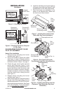
6. Install the inlet tting into the inlet opening
of the gas control valve (see Figure 9). Use
thread sealant on the male pipe threads.
7. Place the burner pan assembly in the
center of the replace oor. Make sure
the front of pan faces forward.
I
L
O
T
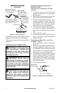
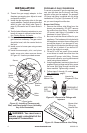
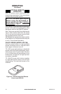
Figure 8 - Gas Control Valve with
Thermocouple and Pilot (Valve May Vary
from Illustration)
Thermopile and Line
Pilot and Line
Gas
Control
Valve
Pressure Tap -
Out (Manifold)
Pressure Tap - In
(Inlet)
PILOT KIT ASSEMbLY
Natural Gas Installation
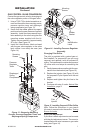
1. Remove burner inlet tting from burner
manifold (see Figure 7).
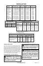
2. Use 10 mm socket to remove the orice
(see Figure 11, page 6). Replace with the
proper orice for your log set. See technical
information charts in Figure 1 on page 2.
3. Thread the gas control valve onto the
burner inlet tting (see Figure 7). Use
thread sealant on the male threads of the
burner inlet tting. Hold the burner inlet
tting with a wrench to prevent overtight-
ening the connection to the burner. Make
sure the control knob is facing the front
(see Figure 7).
4. Replace burner inlet tting into burner
manifold (see Figure 7).
5. Attach the pilot gas line to the pilot outlet of
the gas control valve and tighten. Connect
thermocouple wires to TP and TPTH termi-
nals on gas valve terminal block. See Figure
8. Do not overtighten. If using propane/LP
gas, see Changing Pilot Orice, page 7.
Burner Inlet Fitting
(containing orice)
Gas
Control
Valve
Burner Pan
Assembly
Figure 7 - Installing Gas Control Valve
(Valve May Vary from Illustration)
Control Knob
Figure 9 - Installing Inlet Fitting and Gas
Connector Tube (Valve May Vary from
Illustration)
Gas
Control
Valve
Gas Inlet Fitting
Gas
Connector
Tube
Inlet
Opening