


www.desatech.com
901053-01J6
I
L
INSTALLATION
Continued
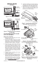
8. Thread the gas supply adaptor to the
replace gas supply pipe. Adjust to most
convenient position.
9. Install the gas connector tube to the gas
supply adapter. Carefully shape tube and
attach to gas inlet tting (see Figure 9,
page 5). Be careful not to cause kinks in
tube.
10. Test for leaks following instructions in your
hearth kit owner’s manual under the sec-
tion Testing Burner for Leaks.
11. Retighten and adjust the location of the
gas control as necessary. The gas control
should be level, with the control knob to
the front.
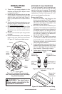
12. Install cover to burner pan using screws
provided.
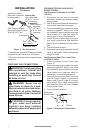
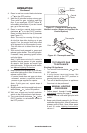
13. Install thermocouple, pilot, and piezo
ignitor cover onto valve cover as shown
in Figure 10. Use the provided screws.
Piezo Ignitor
Screw
Valve
Cover
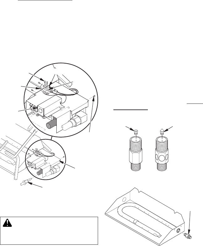
Figure 10 - Installing Thermocouple,
Pilot, and Piezo Ignitor Cover (Valve May
Vary from Illustration)
Thermopile
Ignitor
Pilot
Piezo
Ignitor
Cover
Machine
Screw
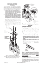
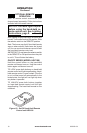
Figure 11 - Burner Inlet Fittings with
Injectors
NATURAL
GAS
FITTING
PROPANE/LP
GAS FITTING
Injector for
Natural Gas
Injector for
Propane/LP Gas
WARNING: You must use a
Figure 12 - Remove Burner Inlet Fitting
Burner Inlet
Fitting for
Natural Gas
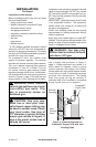
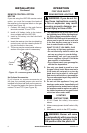
To convert to propane/LP gas, the regulator pres-
sure must be reset also the burner inlet tting
and pilot orice must be replaced. The propane/
LP burner inlet tting is supplied with the orice
installed for a 24" log set. If you have an 18" or 30"
set, you must change this orice also.
1. Remove the burner inlet tting from the
burner pan assembly. DO NOT remove
the orice from this tting. The propane/
LP burner inlet tting is included in the
hardware kit (see Figure 11).
2. Be sure to use the correct orice for your
appliance. The hardware kit included with
this appliance contains three orices with
a cone-like shape. If you have an 18" set,
the orice for the burner inlet tting is red;
for a 30" set, it is black. If you have a 24"
log set, the orice is orange.
3. For an 18" or 30" set, use a 10 mm socket
or nut driver to install the orice from the
propane/LP burner inlet tting. Choose
the correct orice for your log set size and
install using thread sealant.
4.
Using thread sealant (resistant to the action of
propane/LP gas) on larger end of tting, screw
the burner inlet tting through hole and into
burner manifold. Tighten using a wrench.
5 . Follow steps 3 through 13 under Natural
Gas Installation, page 5.