


Fig. 20
Fig. 21
Fig. 22
Fig. 23
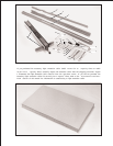
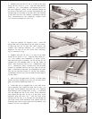
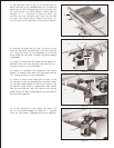
17. Lay the guide tube (B) Fig. 20, on the saw table as
shown, and line up the threaded holes (C) on bottom of
guide tube (B) with the through holes (D) on the front rail
(A). IMPORTANT:If a switch adapter is being used for
Unisaws or 10 Contractor s Saws to mount the
switch to the rail and guide tube, holes (E) are used
to mount the Unisaw switch adapter and holes (F)
will be used for the Contractor s Saw switch adapter.
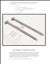
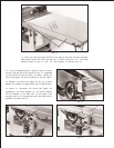
22. On the Contractor s Saw, attach the switch (M)
Fig. 23, to the switch adapter (K) using the 1 long hex
screw (N), flat washer, lockwasher and hex nut supplied.
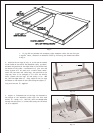
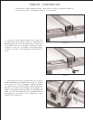
18. Position the guide tube (B) Figs. 21 and 22, on the
front rail and fasten the guide tube to the rail using the
1/2 long hex screws (G) and lockwashers in all of the
holes except the ones used to fasten the switch adapter
if applicable.
19. Figure 21 illustrates the Unisaw switch adapter (H)
mounted to the front rail and guide tube using two 3/4
long hex screws (J) and lockwashers.
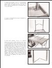
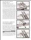
20. Figure 22 illustrates the Contractor s Saw switch
adapter (K) mounted to the front rail guide tube using two
3/4 long hex screws (J) and lockwashers.
21. NOTE: If there is not enough cord (L) Figs. 21 and
22, available to pull out and reposition the switch, simply
cut the cable strap holding the cord to the inside of the
saw cabinet. After switch is repositioned, make certain
that the cord does not come into contact with the saw
blade and use the cable clamp supplied with the fence to
hold the cord in position.
A
B
C
D
F
F
E
E
B
G
G
J
J
H
L
G
L
K
B
J
N
K
M