


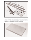
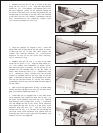

Fig. 12
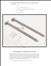
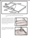
Fig. 13
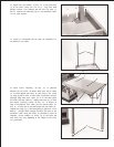
Fig. 14
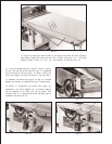
Fig. 15
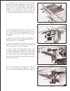
10. Fasten the leg bracket (L) Fig. 12, to the end piece
(J) of the t able using the two 1-1/2 long flat head
Phillips screws, flat washers and hex nut s (M) Figs. 11
and 12. Fasten the remaining leg to the extension table
in the same manner.
11. Figure 13 illustrates the two legs (H) assembled to
the bottom of the t able.
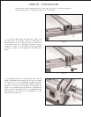
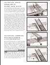
12. Place t able assembly (N) Fig. 14, in position
between the two rails, as shown. Make sure end of table
(O) is flush against saw t able (P) and using a bar clamp
(Q) snug up end of rails to hold t able in position. Using a
straight edge make sure table (O) is in the same plane
and level with saw table (P). Lightly t ap t able up or down
and adjust leveling screws (R) Fig. 15, in bottom of
legs to accomplish this. When you are certain t able (O)
Fig. 14, is level and in the same plane with saw t able (P),
tighten bar clamp (Q) to hold everything in position. Then
drill 1/4 through holes through the front and rear of the
extension t able using the holes (S) provided in rails as
template. NOTE: Number of holes (S) in the front and
rear rails will vary depending on the length of the rails
you purchased.
J
L
M
M
H
P
O
N
S
Q
R