


Fig. 27
Fig. 28
Fig. 29
Fig. 30
ADJUSTING FENCE
PARALLEL TO
MITER GAGE SLOTS
NOTE: Delt a table saws have been aligned at the factory
so that the miter gage slot s in the t able are p arallel with
the saw blade. It is recommended, however, to check
and make certain this alignment is correct before adjust -
ing the fence parallel to the miter gage slot as follows:
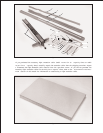
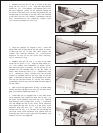
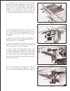
The fence (A) Fig. 27, must be adjusted so it is p arallel to
the miter gage slot s (B). To check and adjust, move
fence (A) until the bottom edge of the fence is in line with
the edge of one of the miter gage slots as shown, and
push down on the fence clamping lever (C). Check to see
if the fence (A) is p arallel to the miter gage slot the entire
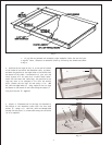
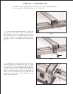
length of the t able. If an adjustment must be made, lift up
fence locking lever (C) and raise fence up off the guide
tube, as shown in Fig. 28. Slightly tighten or loosen one
of the two adjusting screws (D) or (E) Fig. 28, using a
3/16 allen wrench (F), not supplied. Replace the fence
on the guide tube and check again to see if the edge of
the fence is p arallel with the miter gage slot the entire
length of the slot. Repeat this adjustment until you are
sure the fence is p arallel with the miter gage slot.
IMPORTANT:VERY LITTLE MOVEMENTOFSCREWS
(D) AND (E) IS NECESSARY TO ADJUST THE
FENCE PARALLEL WITH THE MITER GAGESLOT.
ADJUSTING CLAMPING
ACTION O F FENCE
LOCKING HANDLE
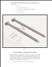
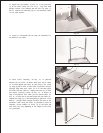
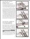
When the fence locking handle (A) is pushed to the down
position, as shown in Fig. 29, the fence assembly (B)
should be completely clamped to the guide tube (C). If
the fence assembly (B) is not completely clamped to the
guide tube (C) when the handle (A) is pushed down, as
shown in Fig. 29, lif t up handle (A) and raise fence
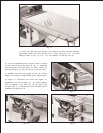
assembly (B) up off the guide tube (C). Slightly tighten
the two adjusting screws (D) and (E) Fig. 30, using the
3/16 allen wrench (F) not supplied. Adjusting screws
(D) and (E) Fig. 30, should be tightened an equal
amount. Replace fence onto the guide tube and re-
check to see if the fence assembly (B) Fig. 29, is com -
pletely tightened to the guide tube (C) with the locking
handle (A) pushed down. Adjust further if necessary.
IMPORTANT:AFTER ADJUSTING THE CLAMPING
ACTION OF THE FENCE LOCKING HANDLE, CHECK
TO SEE IFTHE FENCE IS PARALLEL TO THE MITER
GAGESLOT AND ADJUST IF NECESSARY.
A
C
B
E
F
D
A
C
B
F
D
E