


Dayton Operating Instructions and Parts Manual
8
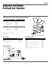
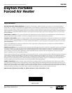
Dayton Portable
Forced Air Heater
®
3VG79B
Maintenance (Continued)
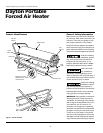
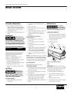
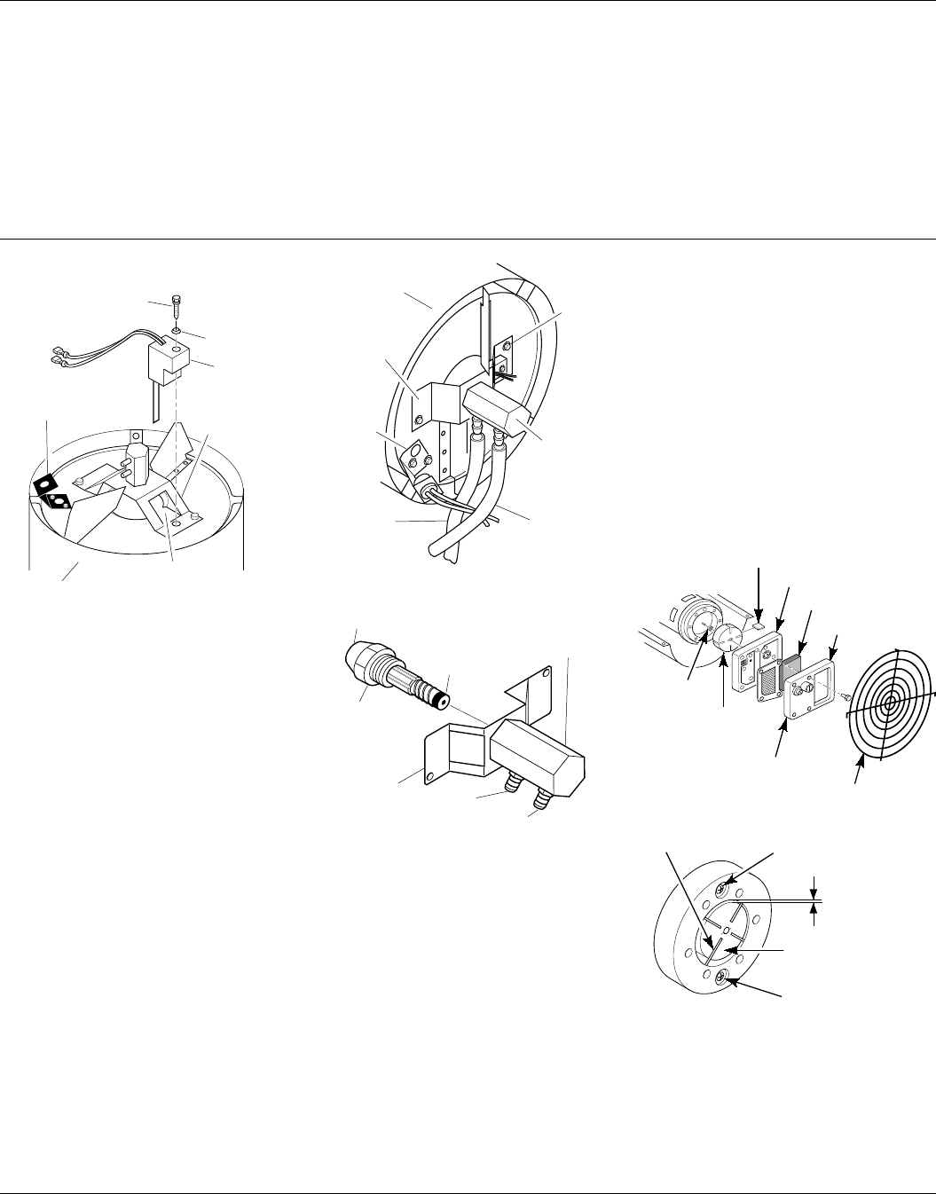
Figure 13 - Ignitor Replacement
Combustion
Chamber
Photocell
Bracket
Ignitor
Ignitor Screw
Nozzle
Adapter
Bracket
Nozzle Adapter
Bracket Opening
Ignitor
Element
Washer
NOZZLE ASSEMBLY
1. Remove combustion chamber and
ignitor by following steps 1 through 7
under Ignitor, page 7.
2. Carefully place the ignitor in a safe
location.
3. Remove two nozzle adapter bracket
screws (See Figure 14).
4. Place hex-shaped aluminum nozzle
adapter into vise (do not overtighten).
5. Carefully remove nozzle from nozzle
adapter using 5/8" socket wrench (See
Figure 15).
6. Blow compressed air through face of
nozzle. This will remove any debris in
nozzle.
7. Inspect nozzle seal for damage.
8. Replace nozzle into nozzle adapter
until nozzle seats. Tighten 80-110
inch-pounds.
9. Attach nozzle adapter bracket to
combustion chamber with two screws
removed in step 3.
10. Repeat steps 9 through 16 under
Ignitor, page 7.
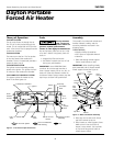
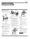
Figure 14 - Removing Air and Fuel Line
Hoses
Combustion
Chamber
Nozzle
Adapter
Bracket
Nozzle
Adapter
Bracket
Screw
Fuel Line
Hose
Nozzle/
Adapter
Assembly
Photocell
Bracket
Air Line
Hose
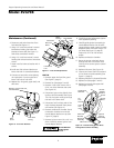
Figure 15 - Nozzle and Nozzle Adapter
Nozzle Face
Nozzle
Nozzle
Seal
Nozzle
Adapter
Bracket
Air Line
Fitting
Fuel Line
Fitting
Nozzle
Adapter
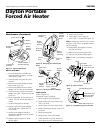
Fan Guard
Filter End Cover
Air Intake Filter
Pump Plate
Blade
Air Output Filter
Rotor
Insert
Gap Adjusting Screw
Gap Adjusting Screw
.003"/.004" Gap
Measured With
Feeler Gauge
Rotor
Blade
PUMP ROTOR
(Refer to Figure 16)
(Procedure if rotor is binding)
1. Remove upper shell (See page 5).
2. Remove filter end cover screws using
5/16" nut-driver.
3. Remove filter end cover and air filters.
4. Remove pump plate screws using 5/16"
nut-driver.
5. Remove pump plate.
6. Remove rotor, insert, and blades.
7. Check for debris in pump. If debris is
found, blow out with compressed air.
8. Install insert and rotor.
9. Check gap on rotor. Adjust to
.003"/.004" if needed (See Figure 17).
NOTE: Rotate rotor one full turn to insure
the gap is .003"/.004" at tightest position.
Adjust if needed.
10. Install blades, pump plate, air filters,
and filter end cover.
11. Replace fan guard and upper shell.
12. Adjust pump pressure (See page 6).
NOTE: If rotor is still binding, proceed as
follows.
Figure 16 - Rotor Location
Figure 17 - Gap Adjusting Screw Locations