


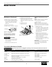
Dayton Operating Instructions and Parts Manual
14
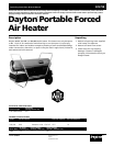
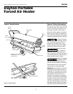
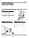
Dayton Portable
Forced Air Heater
®
3VG79B
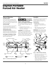
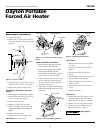
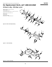
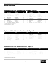
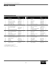
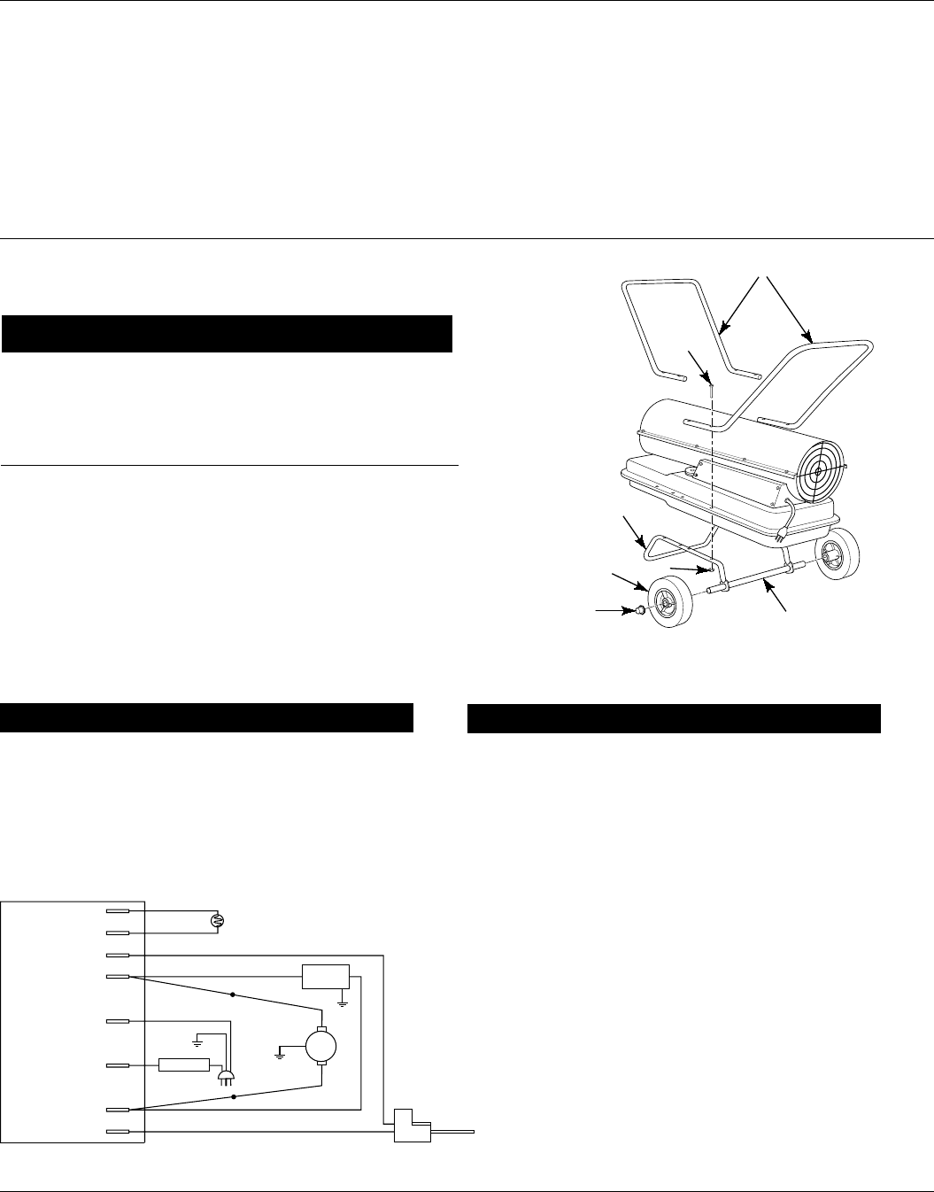
Replacement Parts List for Handle and Wheel Group
Ref. Part
No. Description Number Qty.
1 Handles HA2204 2
2 #10-24 x 1
3
/4" Screw *M12345-33 8
3 Wheel support frame M12831-3 1
4 #10-24 Hex nut *NTC-3C 8
5 Wheel 107426-01 1
6 Cap nut M28526 2
7 Axle M16801-2 1
∆ Thermostat decal 100621-06 1
∆ Tradename decal 097409-13 2
Ignition control 104068-02
Ignitor 102548-06
Filter kit (M11637, M12179, M12244-1, M51150-01) HA3017
Nozzle 100735-13
Rotor/air pump kit (M22456-2, M22009, M8643-2) HA3005
Handle HA2204
Photocell M16656-24
Pump adjustment (M27694, M10993-1, M22997, HA3020
M8940)
Part Numbers
Maintenance Kits
Air gauge kit HA1180
Flame-out control/photocell tester HA1170
Fuel tank filter screen HA2210
Part Numbers
Accessories
2
3
4
5
7
6
(*) Standard hardware item, available locally.
(∆) Not shown.
Figure 24 - Handle and Wheel Assembly
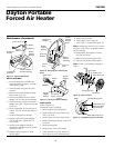
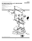
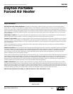
Figure 25 - Wiring Diagram
Wiring Diagram
1
Power Plug
120V/60Hz
Blue
Photocell
Photocell
Ignitor
Motor Return
AC Neutral (L2)
AC Hot (L1)
Motor
Ignitor
Blue
White
White
White
White
Photocell
Ignition Control Assembly
Green
Green
Red
Red
Red
Black
Black
Black
Black
Motor
Ignitor
Solenoid
Valve
Thermostat