


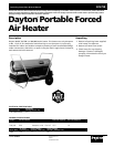

Dayton Operating Instructions and Parts Manual
15
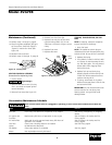
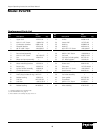
Model 3VG79B
Version B - For Reduction G016.J
®
1. No power to heater
2. Thermostat setting to low
3. Bad electrical connection between motor
and ignition control assembly or ignition
control assembly and power cord
4. Blown fuse on ignition control assembly
5. Binding pump rotor
6. Defective ignition control assembly
7. Defective motor
1. No fuel in tank
2. Pump pressure incorrect
3. Dirty fuel filter
4. Obstruction in nozzle assembly
5. Water in fuel tank
6. Defective fuel valve
7. Bad electrical connection between
ignitor and ignition control assembly
8. Defective ignitor
9. Defective ignition control assembly
1. Pump pressure incorrect
2. Dirty air intake, air output, and/or lint
filter
3. Dirty fuel filter
4. Obstruction in nozzle assembly
5. Photocell assembly not properly
installed (not seeing the flame)
6. Dirty photocell lens
7. Bad electrical connection between
photocell and ignition control assembly
8. Defective photocell
9. Defective ignition control assembly
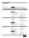
Troubleshooting Chart
Possible Cause(s)
Corrective Action
Never service heater while it is plugged in, operating, or hot.
Severe burns and electrical shock can occur.
Symptom
High Voltage!
Motor does not start five seconds after
heater is plugged in
Motor starts and runs but heater does not
ignite
Heater ignites but ignition control
assembly shuts heater off after a short
period of time
1. Check circuit breaker in electrical panel
2. Turn thermostat knob clockwise to a
higher setting
3. Check all electrical connections. See
Wiring Diagram, page 14
4. See Ignition Control Assembly, page 9
5. If fan does not turn freely, see Pump
Rotor, page 8
6. Replace ignition control assembly
7. Replace motor
1. Fill tank with kerosene
2. See Pump Pressure Adjustment, page 6
3. See Fuel Filter, page 7
4. See Nozzle Assembly, page 8
5. Drain and flush fuel tank with clean
kerosene. See Storing, Transporting, or
Shipping, page 9
6. See Fuel Valve, page 7
7. Check electrical connections. See
Wiring Diagram, page 14
8. Replace ignitor, see page 7
9. Replace ignition control assembly
1. See Pump Pressure Adjustment, page 6
2. See Air Output, Air Intake, and Lint
Filters, page 6
3. See Fuel Filter, page 7
4. See Nozzle Assembly, page 8
5. Make sure photocell boot is properly
seated in bracket
6. Clean photocell lens
7. Check electrical connections. See
Wiring Diagram, page 14
8. Replace photocell
9. Replace ignition control assembly
High Voltage!
High Voltage!