


Dayton Operating Instructions and Parts Manual
7
Model 3VG79B
Version B - For Reduction G016.J
®
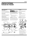
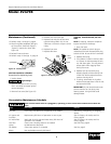
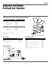
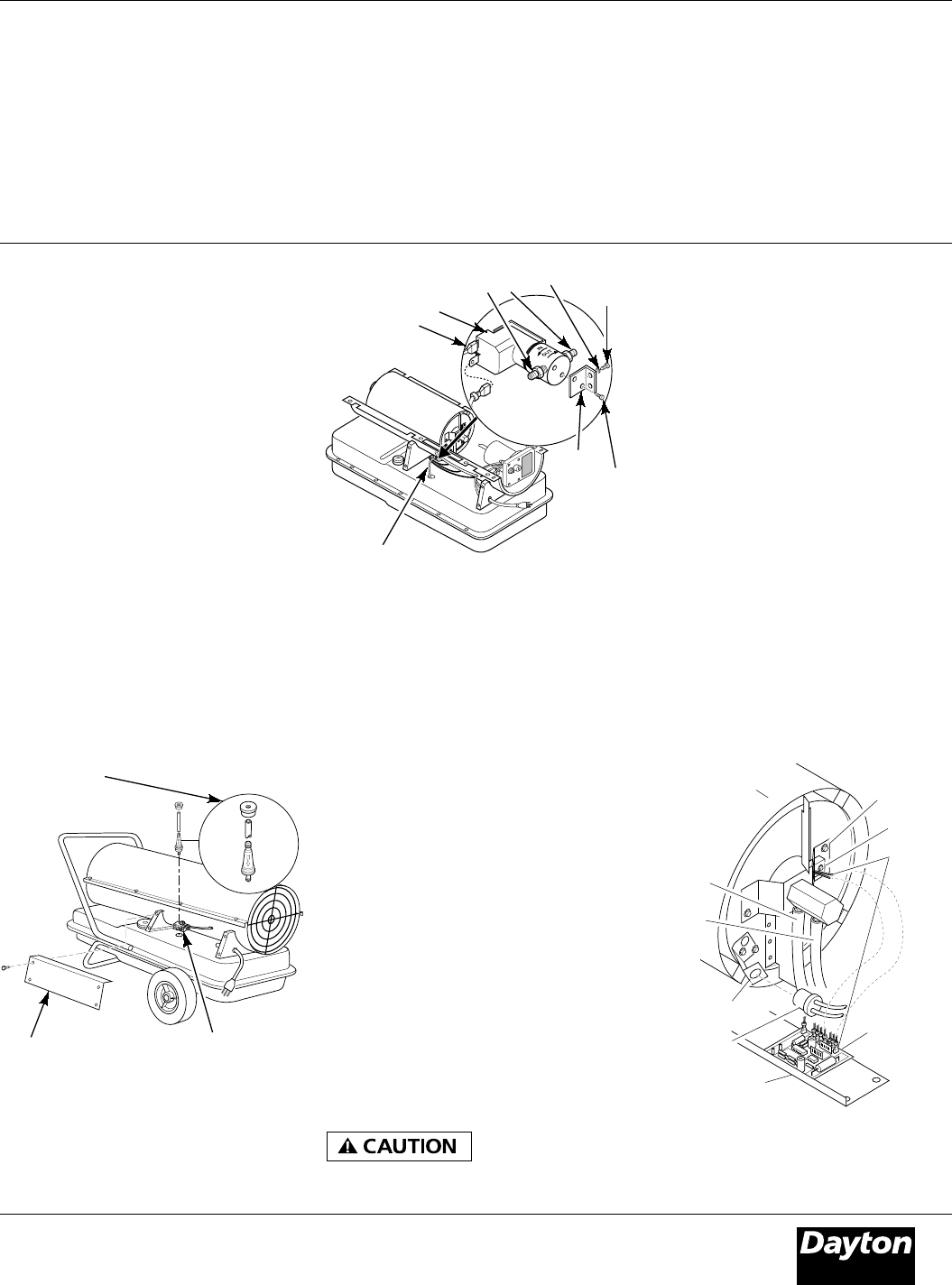
Maintenance (Continued)
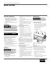
Side
Cover
Bushing, Lower Fuel Line,
and Fuel Filter
Figure 10 - Fuel Filter Removal
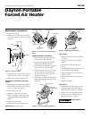
Fuel Valve
Fitting
4. Disconnect red and white wires from
fuel valve (See Figure 11).
5. Using 1/4" nut driver remove 2 screws/
lockwashers holding fuel valve and
bracket to lower shell (See Figure 11).
Save these screws/lock washers.
6. Using 1/4" nut driver remove 2 screws
holding fuel valve to bracket. Save these
screws.
7. Attach new fuel valve to bracket with 2
screws.
8. Install new fuel valve and bracket on
lower shell with 2 screws/lockwashers.
9. Connect red and white wires (polarity
not important). Connect upper and
lower fuel lines to fuel valve.
10. Replace fan, fan guard, upper shell, and
side cover.
Lower Fuel
Line
Electrical
Wires
Fuel Valve
Valve
Fittings
Bracket
Screw
Screw
Figure 11 - Fuel Valve Replacement
Lock Washer
IGNITOR
1. Remove upper shell and fan guard
(See Figure 5, page 5).
2. Remove fan (See pages 5 and 6).
3. Remove 4 side cover screws with a
5/16" nut driver. Remove side cover
(See Figure 10).
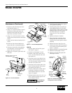
4. Disconnect ignitor wires (black) from
ignition control assembly (See Figure
12). Pull the ignitor wires up through
the hole in the lower shell.
5. Disconnect fuel line hose and air line
hose. Remove photocell from photo-
cell bracket (See Figure 12).
6. Remove combustion chamber. Stand
combustion chamber on end with
nozzle adapter bracket on top (See
Figure 13, page 8).
7. Remove ignitor screw with a 1/4" nut
driver. Carefully remove ignitor from
nozzle adapter bracket.
Do not bend or
strike ignitor
element. Handle with care.
8. Carefully remove replacement ignitor
from styrofoam packing.
9. Carefully guide ignitor into opening in
nozzle adapter bracket. Do not strike
ignitor element. Attach ignitor to nozzle
adapter bracket with screw using a 1/4"
nut driver (See Figure 13, page 8).
Torque 8 to 15 in. lbs. Do not over
torque.
10. Replace combustion chamber.
11. Route the ignitor wires back down
through the hole in the lower shell.
Connect wires to the ignition control
assembly.
12. Replace side cover (See Figure 10).
13. Connect and route fuel line hose and
air line hose to nozzle assembly (See
Figure 14, page 8).
14. Replace photocell in photocell bracket.
15. Replace fan (See pages 5 and 6).
16. Replace fan guard and upper shell
(See pages 5 and 6).
Figure 12 - Disconnecting Ignitor Wires
from Ignition Control Assembly
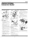
Combustion
Chamber
Photocell
Bracket
Photocell
Assembly
Air
Line
Hose
Fuel
Line
Hose
Ignitor
Wires
Ignitor
Nozzle
Adapter
Bracket
Ignition
Control
Assembly
Side Cover