


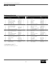
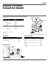

Dayton Operating Instructions and Parts Manual
13
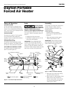
Model 3VG79B
Version B - For Reduction G016.J
®
Ref. Part
No. Description Number Qty.
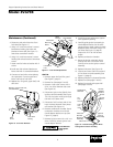
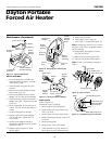
Ref. Part
No. Description Number Qty.
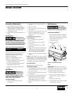
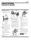
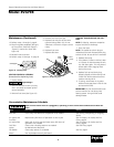
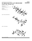
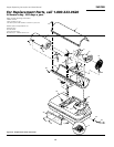
1 Upper shell 107353-04 1
2 #10-16 x 1/2" Screw *100647-01 8
3 Combustion chamber 098512-69 1
4 Photocell bracket 103154-05 1
5 #6-32 x 3/8" Screw *M10908-2 2
6 Photocell assembly M16656-24 1
7 Burner head assembly † 1
8 #10-16 x 1/2" Screw *M11084-27 2
9 Fan 102042-01 1
10 Motor and pump assembly † 1
11 Rubber bumper M50631 2
12 Motor mounting bracket 101206-01 1
13 Button plug 101695-01 1
14 Ignition control assembly 104068-02
15 1/4-20 Hex lock nut *NTC-4C 2
16 Fan guard 102756-01 1
17 Drain plug (includes O ring) M27417 1
18 Rubber bushing 103523-01 1
19 Fuel line M51345-03 1
20 Fuel filter **M51150-01 1
21 Fuel line tube M51345-04 1
22 Rubber bushing M10990-3 1
23 Airline M50814-03 1
24 Lower shell 107353-08 1
25 Bushing M30865-02 1
26 Bushing M50104-01 1
27 #10-16 x 1/2" Screw *M11084-27 6
28 Clip nut M11271-8 8
29 #8-32 x 3/8" Screw *M10908-14 1
30 Fuel tank 098513-105 1
31 Fuel cap (includes gasket) 097702-01 1
32 P.C. board support 102349-01 5
33 Strain relief bushing M11143-1 1
34 Power cord 098219-38 1
35 Side cover 107333-04AA 1
36 #10-16 x 1/2" Screw *M11084-27 4
37 Special screw 099230-01 2
38 #10-16 x 1/2" Screw *M11084-27 2
39 Fuel valve assembly † 1
40 Foam gasket 097785-04 2
41 Thermostat 097657-03 1
42 #6-32 x 1/4" Screw M10908-1 2
43 Thermostat knob 104905-01 1
44 Wire assembly 079010-35 1
(*) Standard hardware item, available locally.
(**) See MAINTENANCE KITS, page 14.
(†) Not available as an assembly, see pages 10 and 11.
Replacement Parts List