


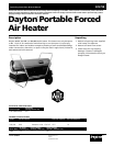
Dayton Operating Instructions and Parts Manual
5
Model 3VG79B
Version B - For Reduction G016.J
®
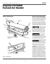
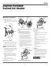
4. Place handles on top of fuel tank
flange. Insert screws through handles,
fuel tank flange, and wheel support
frame. Attach nut finger tight after
inserting each screw.
5. After inserting all screws, tighten nuts
firmly.
Follow the mini-
mum fresh, outside
air ventilation requirements. If proper
fresh, outside air ventilation is not
provided, carbon monoxide poisoning
can occur. Provide proper fresh, outside
air ventilation before running heater.
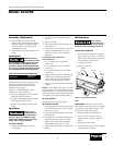
FRESH AIR OPENING REQUIREMENTS
Square Feet
Heater Size Opening
200,000 Btu/Hr 6.0
Ventilation
Review and
understand the
warnings in the Safety Information
Section. They are needed to safely
operate this heater. Follow all local
codes when using this heater.
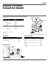
TO START HEATER
1. Follow all ventilation and safety
information.
Operation
Provide a fresh air opening at least three
square feet for each 100,000 Btu/Hr
rating. Provide extra fresh air if more
heaters are being used.
Example: A 200,000 Btu/Hr heater
requires one of the following:
• a two-car garage door (16 foot wide
opening) raised five inches
• a single-car garage door (9 foot wide
opening) raised eight inches
• two 30-inch windows raised fifteen
inches
TO STOP HEATER
Unplug extension cord from outlet.
TO RESTART HEATER
1. Unplug extension cord from outlet and
wait 10 seconds (two minutes if heater
has been running).
2. Turn thermostat knob clockwise to the
HIGH position.
3. Plug extension cord into standard 120
volt/60 hertz, three-hole, grounded
outlet. Note: Ignitor will preheat for
five seconds then heater will start.
4. Adjust thermostat knob to the desired
setting.
2. Fill fuel tank with Kerosene or No. 1
fuel oil.
3. Attach fuel cap.
4. Turn thermostat knob clockwise to the
HIGH position.
5. Plug power cord of heater into three-
prong, grounded extension cord.
Extension cord must be at least six
feet long.
EXTENSION CORD WIRE SIZE
REQUIREMENTS
• 6 to 10 feet long, use 18 AWG
rated cord
• 11 to 100 feet long, use 16 AWG
rated cord
• 101 to 200 feet long, use 14 AWG
rated cord
6. Plug extension cord into standard 120
volt/60 hertz, three-hole, grounded
outlet. Note: Ignitor will preheat for
five seconds then heater will start.
7. Adjust thermostat knob to the desired
setting.
NOTE: A cold heater may affect the ther-
mostat setting. This thermostat is a general-
heating control. It is not intended for pre-
cise temperature control. Adjust thermostat
until heater cycles at the desired setting.
Assembly (Continued) Maintenance
Never service
heater while it is
plugged in, operating, or hot. Severe
burns and electrical shock can occur.
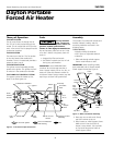
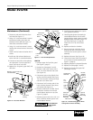
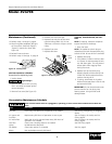
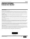
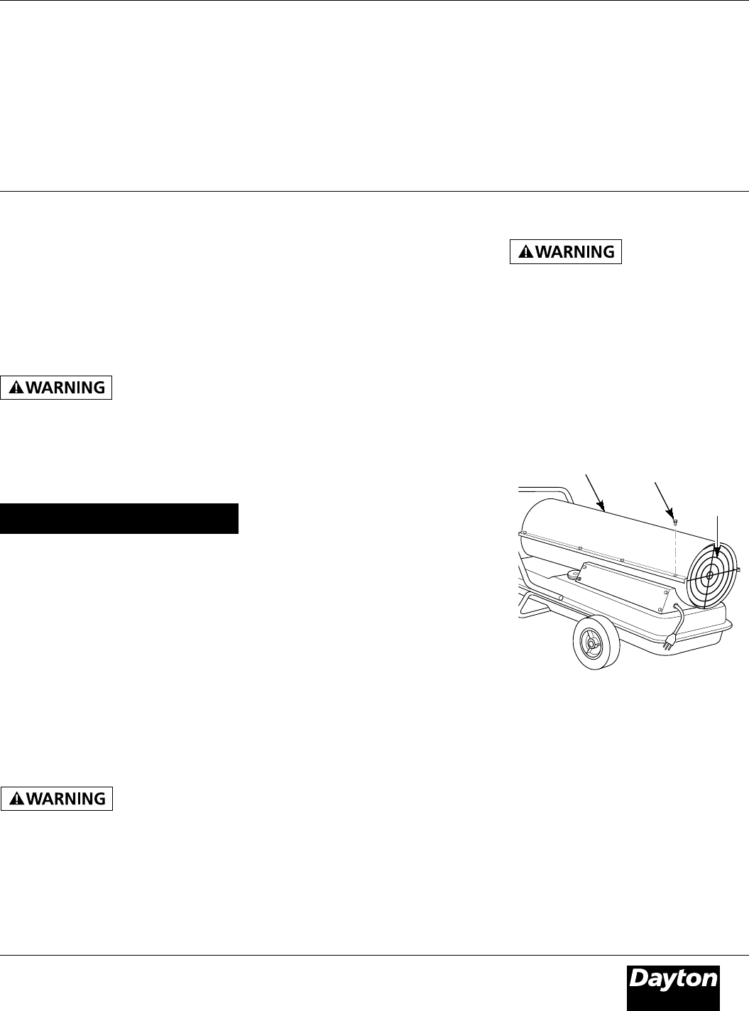
UPPER SHELL REMOVAL
1. Remove screws along each side and
top of heater using 5/16" nut-driver.
These screws attach upper and lower
shells together (See Figure 5).
2. Lift upper shell off.
3. Remove fan guard.
Figure 5 - Upper Shell Removal
Upper
Shell
Fan
Guard
Screw
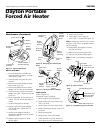
FAN
IMPORTANT: Remove fan from motor
shaft before removing motor from heater.
The weight of the motor resting on the
fan could damage the fan pitch.
1. Remove upper shell (See Figure 5).
2. Use 1/8" Allen wrench to loosen
setscrew which holds fan to motor
shaft.
3. Slip fan off motor shaft.
4. Clean fan using soft cloth moistened
with Kerosene or solvent.