


23
Glow Boy Pellet & Biomass www.glowboystoves.com 23
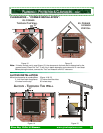
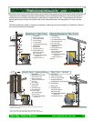
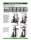
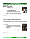
8”
6”
Wall Band /
Support Brkt
every 5’
Wood Frame
Construction
Ceiling Support /
Firestop Spacer
Stand Off
Part ACISOVL
3” minimum
air gap
V
ertical Vent Installation
8”
6”
Wall Band /
Support Brkt
every 5’
Wood Frame
Construction
Ceiling Support /
Firestop Spacer
Stand Off
Part ACISOVL
3” minimum
air gap
V
ertical Vent Installation
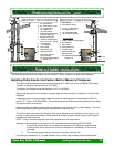
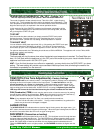
Interior
Chase
Metal
Chase Cap
Storm Collar
Rain Cap
Clean Out Tee
Clean Out Tee
10’
2’
Shroud
Wood Surround
Wood Surround
Shroud
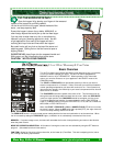
4
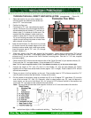
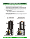
8”
6”
Wood Frame
Construction
Stand Offs
Part ACI-3HZ
6”
2” Min.
Air gap
Horizontal Vent Installation
Exterior Wall
Wood Surround
Shroud
3” minimum
air gap
Wall Band /
Support Brkt
every 5’
Clean Out Tee
10’
2’
4
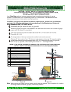
12”
8”
6”
Wood Frame
Construction
Stand Offs
Part ACI-3HZ
6”
2” Min.
A
ir gap
Exterior Wall
Wood Surround
Shroud
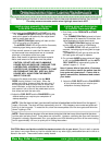
When constructing a chase
ensure adequate insulation,
vapor barrier, drywall and
caulking is used. Keep in
mind you are building
another room to your home.
You want it to be as energy
efficient as the rest of your
home.
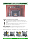
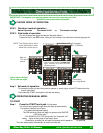
Minimum
Required
Traditional
Unit Only
Traditional
Minimum
BayView
Unit Only
Side Clearance
3 in 22 1/4 in 28 1/4 in 24 in
Top Clearance
2 in 18 3/4 in 20 3/4 in 19—23 in
Back Clearance
6 in 11 3/4 in 17 3/4 in 10 3/4 in
Bayview
Minimum
30 in
25—29 in
16 3/4 in
TIP: To allow for much
easier removal of the
appliance and for clean-
ing and maintenance , it
is highly recommended
to make your framed
opening as large as
possible. It is suggested
to use your overall
Shroud Enclosure
measurements and
construct your framing to
be 1 to 2 inches smaller
than the shroud.
MINIMUM FRAMING DIMENSIONS:
The MINIMUM framed opening or clearances to all combustibles are as follows:
(Combustibles include drywall or any paper backed product, wood framing, insulation, vapor barrier, or any
other product as set out in our local building code.)
Note: The BACK frame distance will be effected by the depth of the framed wall as well as the installation of
the exhaust venting.
B
B
UILT
UILT
-
-
I
I
N
N
I
I
NSERT
NSERT
I
I
NSTALLATION
NSTALLATION
. . . C
. . . C
ON
ON
’
’
T
T