


17
I
I
NSTALLATION
NSTALLATION
—
—
F
F
REESTANDING
REESTANDING
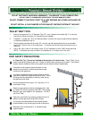
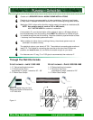
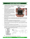
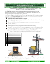
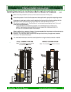
THROUGH THE WALL, DIRECT VENT INSTALLATION. (not preferred) (Figure 18)
1. Select the location for your stove, design the
exhaust system and determine the brand and
size of "PL" vent to be used.
2. Position the floor pad.
3. Following the "PL" vent manufacturer's specifi-
cations, mark and cut a hole through the wall to
accommodate the wall thimble, (F), and the out-
side air pipe, (I), if outside air is to be used. Re-
member that the outside air intake must be lo-
cated no closer than 12” from the vent exhaust.
Try to avoid cutting wall studs, and use extreme
caution to avoid cutting into power or water lines
within the wall of your home.
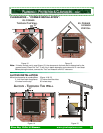
4. Install the wall thimble, (F). Be sure to run a bead
of silicone around the outside edges of the wall
thimble to reduce drafts, both inside and outside.
Insert the proper size of "PL" vent, (E), through
the wall thimble, (F).
5. Place your stove on the floor pad, close to its final position. Leave room to connect the "PL" vent to
“Quick Connect” end collar. If not already factory installed, Install the gasket (B) and “Quick Connect”
exhaust end (C) to your stove to the “Quick Connect” mounting plate. Use the 4 x 7/16” nuts, supplied
and secure tightly.
6. Place a bead of RTV silicone around the end collar of the “Quick Connect” of your stove's exhaust, (C).
Firmly push the “PL” vent pipe adaptor (J) into the bead of RTV silicone.
Note: If 4" PL vent is required, use an 3” to 4” Pipe Adaptor Increaser, (J), on the stove exhaust pipe.
7. Connect the length of "PL" vent, (E), that is in the thimble, (F), onto the pipe adaptor (D). Fasten
together with at least three sheet metal screws (approx. 3/8” in length). Place a bead of RTV silicone
around the connection.
8. Place your stove in its final position on the pad. Place another bead of RTV silicone around the “PL”
vent (E) and the inside of the wall thimble, to stop cold air drafts.
9. On the outside of the building, place an exhaust cap (G) or a 45 degree "PL" type elbow, (G), onto the
end of the horizontal "PL" vent, (E). Optionally, place a rodent screen cap, (G), (may be required in
some locals), on the end of the elbow, (G). run a bead of RTV silicone around all connections and
around the “PL” vent pipe and the outside of the wall thimble.
Note: The end of the exhaust pipe must extend a minimum of 12” from the outside of the building.
Note: Most horizontal, through the wall installations may require a Clean-out Tee and minimum 3’
vertical rise of pipe, inside or outside the building. See Next Page.
Glow Boy Pellet & Biomass www.glowboystoves.com 17
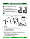
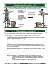
6”
1”
10”
6”
2”
12”
HROUGH HE ALLT T W
6” 6”