


22
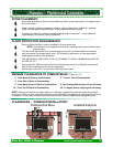
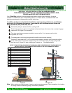
CAUTION: DO NOT BLOCK ANY VENT OPENINGS
PELLET VENT MUST MAINTAIN A MINIMUM 3” CLEARANCE TO ANY COMBUSTIBLE.
(INSTALL VENT AT CLEARANCES SPECIFIED BY THE VENT MANUFACTURER).
DO NOT CONNECT THE PELLET VENT TO A VENT SERVING ANY OTHER APPLIANCE OR
STOVE.
DO NOT INSTALL A FLUE DAMPER IN THE EXHAUST VENTING SYSTEM OF THIS UNIT.
THE APPLIANCE MUST BY PLACED ON A NON-COMBUSTIBLE SURFACE,
BOTH ON THE HEARTH AND WITHIN THE FRAMED AREA.
(REFER TO FLOOR PROTECTION REQUIREMENTS IN THIS MANUAL.)
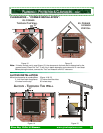
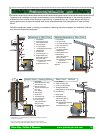
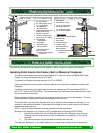
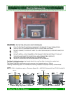
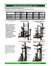
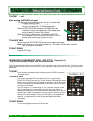
The Glow Boy Series Inserts may be framed directly into a wall as either a horizontal or vertical vent
installation. (see figure 27, 28).
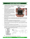
The exhaust installation requirements are the same as for a freestanding stove. Refer to
“Installing Freestanding Stove” for information concerning installation and proper hook-up of the exhaust.
NOTE: Built-in Installations require: Enclosure Spacer Kit — #ACI-3HZ Horizontal Kit or ACI-3VL Vertical Kit
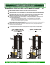
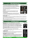
24”
18 3/4”
+
+
6 1/2”
7 3/4”
8 1/4”
3 ½”
Exhaust
Air Inlet
24”
24 3/4”
12 1/4” 10 3/4”
24”
Shroud 1”
12 1/4” 10 3/4”
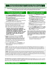
+
Exhaust
26”
+
24”
6 ½”
Exhaust
+
Air Inlet
8 1/4”
7 3/4”
3 ½”
Bay View Insert / Built-InClassic Step Top Insert / Built-In
19”
-
23”
Adjustable
Hopper
Shroud 1”
Glow Boy Pellet & Biomass www.glowboystoves.com 22
B
B
UILT
UILT
-
-
I
I
N
N
I
I
NSTALLATION
NSTALLATION