


34
34
8) Flow control valve (Required under some conditions) – The fl ow control valve prevents fl ow through the system unless the
circulator is operating. A fl ow control valve may be necessary on converted gravity systems to prevent gravity circulation.
Flow control valves are also used to prevent “ghost fl ows” in circulator zone systems through zones that are not calling for
heat.
9) Isolation Valves (Optional) – Isolation valves are useful if the boiler must be drained, as they will eliminate having to drain
and refi ll the entire system.
10) Drain Valve – The drain valve is shipped in the boiler parts bag. Install it in the location shown in Figure 1.
B. Piping for Special Situations
Certain types of heating systems have additional requirements. Some of the more common variations follow:
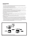
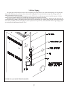
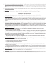
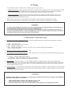
1) Indirect Water Heaters – Figure 27 shows typical indirect water heater piping. Boiler piping is the same as for any two-zone
system. Figure 27 shows circulator zoning, which is usually preferred for indirect water heaters. Size the circulator and
indirect water heater piping to obtain the boiler water fl ow through the indirect water heater called for by the indirect water
heater manufacturer. The standard CWD control system will operate two circulator zones. See the Wiring section of this
manual.
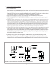
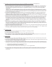
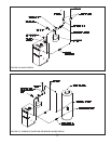
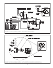
2) Gravity and “Large Water Volume” Systems – The piping shown in Figure 28 will minimize the amount of time that the
boiler operates with return temperatures below 120F on these systems. A bypass is installed as shown to divert some supply
water directly into the return water. The bypass pipe should be the same size as the supply. The two throttling valves shown
are adjusted so that the return temperature rises above 120F during the fi rst few minutes of operation. A three-way valve
can be substituted for the two throttling valves shown. If the circulator is mounted on the supply, the bypass must be on the
discharge side of the circulator.
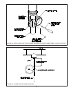
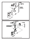
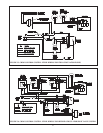
3) Low Temperature Systems – Some systems, such as radiant tubing systems, require the system water temperature to
be limited to a value below the temperature of the water leaving the CWD. These systems also typically have return
temperatures well below the 120F minimum.
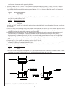
Figure 29 illustrates the use of a heat exchanger to connect a CWD boiler to this type of system. The heat exchanger will
permit the transfer of heat from the boiler water to the low temperature system while holding the system supply and boiler
return temperatures within their limits. For this system to work properly, the heat exchanger must be properly sized and
the correct fl ow rates are required on either side of the heat exchanger. Consult the heat exchanger manufacturer for sizing
information. The water in the boiler is completely isolated from the water in the system. This means that separate fi ll and
expansion tanks are required for the heating system loop.
There are several other ways to connect low temperature systems to the non-condensing boilers like the CWD such as
four way mixing valve and variable speed injection pumping systems.
4) Systems containing oxygen – Many hydronic systems contain enough dissolved oxygen to cause severe corrosion damage
to a cast iron boiler such as the CWD. Some examples include:
• Radiant systems that employ tubing without an oxygen barrier.
• Systems with routine additions of fresh water.
• Systems which are open to the atmosphere.
If the boiler is to be used in such a system, it must be separated from the oxygenated water being heated with a heat
exchanger as shown in Figure 29.
Consult the heat exchanger manufacturer for proper heat exchanger sizing as well as fl ow and temperature requirements.
All components on the oxygenated side of the heat exchanger, such as the pump and expansion tank, must be designed for
use in oxygenated water.
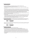
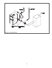
5) Piping with a Chiller – If the boiler is used in conjunction with a chiller, pipe the boiler and chiller in parallel as shown in
Figure 30. Use isolation valves to prevent chilled water from entering the boiler.
6) Air Handlers – Where the boiler is connected to air handlers through which refrigerated air passes, use fl ow control valves
in the boiler piping or other automatic means to prevent gravity circulation during the cooling cycle.