


27
27
6) Assembly of Heat Fab Saf-T Vent EZ Seal:
a) Saf-T Vent General Notes:
These instructions cover the installation of Saf-T Vent EZ Seal. Saf-T Vent EZ Seal piping has integral gaskets installed in
the female ends of the pipe which seal the joints.
• In general, Saf-T Vent pipe sections may not be cut. Exceptions to this are the Saf-T Vent slip connector and connections
to the boiler vent collar and Crown coaxial terminal. In these cases, use a sharp pair of aviation snips, an abrasive cut-off,
or a plasma cutter. See the Saf-T Vent instructions for information on cutting the slip connector.
• Orient Saf-T Vent components so that the arrows on the piping labels are in the direction of fl ue gas fl ow.
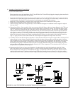
• Support horizontal piping sections at intervals of 6 feet or less.
• Vertical venting systems must be supported by at least one Heat Fab support. An additional vertical support is required
after any offset.
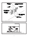
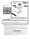
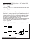
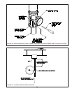
b) Connection to Boiler – Start assembly of the vent system at the boiler. Remove the hose clamp shipped on the CWD vent
collar. Bend the three hose clamp tabs on this collar outward slightly. Cut the male “spigot” off of the fi rst piece of pipe
(Fig 21). If necessary, crimp the cut end of the pipe so that it can be inserted at least 1” into the collar. Clean the exterior
of the male end of the fi rst piece of pipe and the inside of the vent collar on the boiler with an alcohol pad. On the male
end of the pipe, apply a ¼” wide bead of high temperature silicone approximately ½ inch from the male end of the pipe.
Also apply a ¼” bead of silicone along the fi rst 2 ½” of the longitudinal weld. Insert the male end of the pipe into the
boiler vent collar until it bottoms out. Apply an additional bead of silicone over the outside of the joint and smooth out
(Fig 21). Apply silicone over the seams in the vent collar. Replace and tighten the clamp on the vent collar.
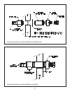
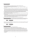
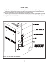
c) Assembly of Saf-T Vent EZ Seal Vent Components - Clean the male end of the next piece of pipe with an alcohol pad and
make sure that it is free of burrs. Check the female end of the fi rst piece of pipe to make sure that the gasket is in place
and is undamaged. Using a slight twisting motion, insert the male end of the second fi tting into the female end of the fi rst
fi tting, taking care not to dislodge or cut the factory gasket. In extremely arid conditions, it may be easier to assemble
these fi ttings if the gasket is moistened with water prior to assembly. Bend the locking tabs over the locking ring on the
adjacent piece of pipe. Repeat these steps for the remaining Saf-T-Vent components. If a termination elbow is used, use
this procedure to complete the exhaust system.
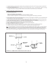
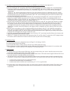
d) Connection of Saf-T Vent to Crown coaxial terminal - Cut the locking tabs off of the female end of the Saf-T Vent
pipe to be joined to the co-axial terminal. Apply a ¼” bead of silicone around the terminal connection about ¼” from
the end. Slip the Saf-T Vent pipe over the terminal and apply a second bead of silicone over the joint. Silicone must be
applied even though there is a gasket on the female end of the pipe. Smooth the excess silicone over the joint, making
sure that there are no visible voids in the silicone. Tighten the terminal clamp. Allow the silicone to cure per the silicone
FIGURE 21: SAF-T VENT EZSEAL CONNECTION TO VENT COLLAR