


29
29
8) Assembly of Protech FasNSeal
a) FasNSeal General Notes:
• Do not cut 4” FasNSeal pipe. Consult FasNSeal instructions for method of cutting other 3” pipe.
• Orient FasNSeal vent components so that the arrows on the piping labels are in the direction of fl ue gas fl ow.
• Support horizontal piping sections at intervals of 6 feet or less.
• Vertical venting systems must be supported by at least one FasNSeal support. An additional vertical support is required
after any offset.
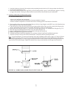
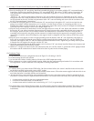
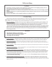
a) Remove the hose clamp shipped on the CWD vent collar. Bend the three hose clamp tabs on this collar outward slightly.
Clean the exterior of the male end of the fi rst piece of pipe and the inside of the vent collar on the boiler. Remove dirt,
grease, and moisture from the surfaces to be sealed. Dry surfaces or allow to dry thoroughly. On the male end of the pipe,
apply a ¼” wide bead of high temperature silicone approximately 1/4 inch from the male end of the pipe. Insert the male
end of the pipe into the boiler vent collar until it bottoms out. Apply an additional bead of silicone over the outside of the
joint and the seams on the vent collar and smooth out (Fig 22). Replace and tighten the clamp on the vent collar.
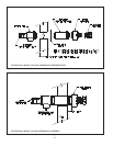
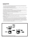
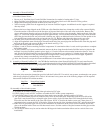
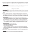
b) All other joints in the FasNSeal venting system rely on a gasket in the female end of the pipe for a proper seal.
c) Align the longitudinal seam of both pipes. Insert the male end of the second pipe into the female end of the fi rst pipe until
the bead on the male end contacts the fl are on the female end (Fig. 17b).
d) Tighten the locking band with a nut driver.
e) Repeat (c) and (d) for the remaining FasNSeal components. If a termination elbow is used, use this procedure to complete
the exhaust system.
f) To join FasNSeal to a Crown coaxial terminal, remove the hose clamp from the female FasNSeal end to be joined to the
terminal. Leave the FasNSeal gasket in place. Apply a ¼” bead of silicone to the terminal connection about ¼” from its
end. Slip the FasNSeal female end over the terminal end so that there is an overlap of 1 ¾ inches. Apply and smooth
silicone over the outside of the joint including the rectangular hose clamp opening in the FasNSeal pipe. Tighten the
terminal hose clamp to mechanically lock the pipe onto the terminal.
g) Allow the silicone to cure per the silicone manufacturer’s instructions before operating the boiler.
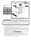
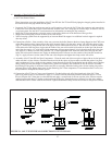
9) Assembly of Protech FasNSeal W2 - On CWD Boiler installations where Protech FasNSeal W2 is used, some Protech
FasNSeal (single wall pipe) will always be required between the boiler and the FasNSeal W2. Install this pipe as described
above. On all systems, the following components will be needed to adapt from Protech FasNSeal to FasNSeal W2:
Vent Size Protech Part Number
3” FSA-SWDW3
4” FAS-SWDW4
Follow the joint connection instructions provided with the FasNseal W2. In vertical vent systems, terminate the vent system
with the cap called for FasNSeal W2 in Table 4. In horizontal vent systems one of the following adapters will be required
between the FasNSeal W2 and the terminal:
Vent Size Protech Part Number
3” FSA-DWSW3
4” FAS-DWSW4
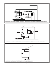
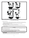
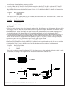
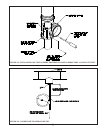
10) Assembly of the air intake system:
a) Assemble the air intake system using either galvanized or PVC pipe.
b) If PVC piping is used, use PVC cement to assemble the PVC intake system components.
c) If galvanized piping is used, use at least two sheet metal screws per joint. Seal the outside of all joints.
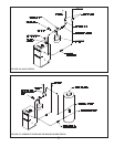
d) A 4” galvanized smoke pipe will fi t inside the inlet collar on the CWD boiler. Depending upon the exact OD of the
pipe used, it may be necessary to crimp this pipe. Secure with a single #10 sheet metal screw through the hole in the
inlet collar and seal the outside of the joint with silicone. If PVC is used for the intake system, use a short piece of 4”
galvanized pipe to connect the PVC to the boiler. Silicone the outside of the joint between the PVC and galvanized pipe.
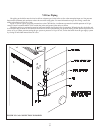
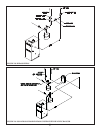
e) Either PVC or galvanized pipe will fi t over the combustion air connection on the Crown coaxial terminal. Secure the
pipe to the terminal with at least two #10 sheet metal screws. Seal the outside of the joint between the inlet pipe and the
coaxial terminal.
f) Two 90-degree elbows may be used to make the 180-degree air intake termination elbow used on vertical direct vent
installations.