


30
30
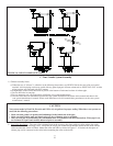
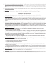
11) Assembly of Vertical Coaxial Vent System Using Crown #500005 Coaxial Vent Kit (Vent Option #11)
a) Start by installing the “B” vent piping. Install and assemble this piping in accordance with the “B” vent manufacturer’s
instructions. Seal the joints between sections of “B” vent with GE RTV 106 or Dow 732 RTV sealant. Consult the “B”
vent manufacturer’s instructions for the clearance to combustibles (typically 1”) as well as for fi re stop and support
requirements.
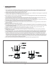
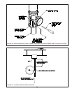
Install a 5” “B” vent Tee on the bottom of the run of “B” vent as shown in Figure 12. Extend the run of “B” vent far
enough above the roof so that the bottom of the air intake hood will be at least one foot above the normal snow line that
can be expected on the roof. Seal the roof penetration with a “B” vent roof fl ashing and storm collar in accordance with
the “B” vent manufacturer’s instructions.
b) Assemble the vent piping that is to be run inside the “B” vent and drop it through the “B” vent. Join and seal the vent
piping in accordance with the instructions 4, 5,6 or 8 above. Use the longest sections of vent piping possible so as to
minimize the number of joints inside the “B” vent. Temporarily support the vertical section of vent pipe from underneath
so that the top of the vent pipe is at the correct height (Figure 12).
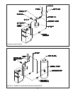
c) Slip the Crown concentric air intake hood over the vent pipe and seat it on the “B” vent. Secure the concentric air intake
hood to the “B” vent with at least three sheet metal screws. Install a storm collar compatible with the vent system over
the vent pipe. Secure and seal it in accordance with the vent manufacturer’s instructions. Note: this collar provides a
watertight seal between the vent piping and the concentric air intake hood and also supports the vent piping. Once the
storm collar is installed, remove the temporary vent support. Install a compatible rain cap on the top of the vent system
(Table 4).
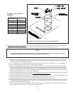
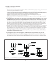
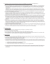
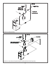
d) Slip the Crown vent support over the vent pipe protruding from the bottom of the “B” vent. Orient the vent support so
that it will be possible to tighten the gear clamp by reaching through the side opening in the “B” vent Tee (Figure 23).
Attach the vent support to the “B” vent Tee with at least three sheet metal screws. Tighten the gear clamp. Seal all joints
in between the vent support, the vent pipe, and the “B” vent.
e) Install the vent piping between the boiler and the vertical section of “B” vent already installed. Observe the clearance and
support requirements in the installation manual.
f) Install a 5 x 4 single wall reducer in the side connection of the “B” vent Tee. Install 4” galvanized or PVC piping between
this reducer and the combustion air intake on the boiler. Seal all joints in the air intake piping.
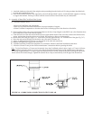
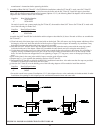
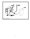
12) Condensate Traps:
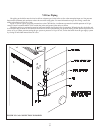
a) Trap should have the basic confi guration shown in Figure 24. All tubing is 3/8 I.D.
b) All drain tubing must be acid resistant.
c) At least the fi rst 6 inches of tubing must be silicone with a 300F temperature rating.
d) Pipe condensate to a drain or other suitable location. Make sure that condensate disposal method is in accordance with
local regulations. Ensure condensate is not subjected to freezing temperatures.
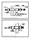
13) Rodent Screens:
a) A rodent screen is provided with the CWD boiler. On direct exhaust boilers, this screen is installed in the air inlet collar
on the boiler and held in place with screws or RTV sealant.
b) The Crown coaxial terminal has integral inlet and exhaust rodent screens. The rodent screen supplied with the boiler is not
used when the boiler is installed with the coaxial terminal.
c) In horizontal direct vent installations using termination elbows or tees, the rodent screen provided is mounted in the air
inlet elbow. A second screen is required for the exhaust elbow. This second screen can be any one of the following items:
• A rodent screen provided by the vent system manufacturer.
• A second Crown rodent screen (Crown #60-601).
• A rodent screen made of stainless steel screen having a ½” (2 x 2) or greater mesh.
d) In vertical direct vent or direct exhaust systems, no rodent screen is required on the exhaust terminal. The rodent screen
is installed either on the 180-degree inlet elbow (direct vent installations) or on the boiler inlet collar (direct exhaust
installations).