


13
13
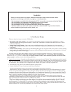
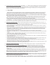
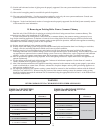
3) Permitted Terminals for Horizontal Venting (Vent Options 1 - 5) - Table 3a shows permitted types of terminals for both the
vent and air inlet systems. On horizontal direct vent systems using 4” air inlet pipe (Vent Options 1 and 2), the following
Crown co-axial terminals may be used. These terminals have the advantage of requiring only one wall penetration. Part
numbers for the Crown coaxial terminals are as follows:
• 3” Vent - 50-003
• 4” Vent - 50-004
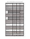
When separate vent and air intake terminals are used, or when the boiler uses indoor combustion air, the vent terminal
is either a tee or an elbow supplied by the vent system manufacturer and equipped with a rodent screen. Vent system
manufacturer’s part numbers for these fi ttings are shown in Table 4. In some cases, the elbows and tees shown in Table 4
require separate adaptors and/or rodent screens. When this is the case, vent manufacturer part numbers for these additional
parts are shown in Table 4 along with the termination fi tting.
When Heat Fab Saf-T Vent SC is used, the Heat Fab 5300CI or 5400CI fi tting is used between the last piece of Saf-T
Vent CI and the terminal. These fi ttings physically adapt from the CI pipe to the terminal and also provide ventilation
openings which must remain open for the Saf-T Vent CI to maintain its clearance rating.
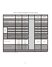
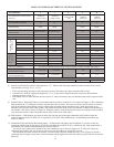
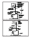
Except when the Crown 50-003 or 50-004 coaxial terminals are used, the air intake fi tting on a horizontal direct vent
system (Options 1 - 2) is always a 90 degree elbow with a rodent screen. This elbow is made out of the same material as the
rest of the air inlet system (either galvanized or PVC) and is installed as shown in Figure 8a.
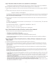
4) Horizontal vent terminal location - Observe the following limitations on the vent terminal location (also see Fig 15a - d):
• Direct exhaust installations (installations using indoor combustion air) - Exhaust terminal must be at least 4 feet below or
4 feet horizontally from any window, door, or gravity air inlet into the building.
• Direct vent installations – Exhaust elbow or coaxial terminal must be at least 1 foot from any door, window, or gravity
inlet into the building.
• Direct vent installations using termination elbows – Maintain the correct clearance and orientation between the inlet and
exhaust elbows. The elbows must be at the same level and their center lines must be between 12 and 36 inches apart.
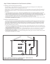
• The bottom of the exhaust elbow, tee, or coaxial terminal must be at least 12” above the normal snow line. In no case
should it be less than 12” above grade level.
• The bottom of the exhaust elbow, tee, or coaxial terminal must be at least 7 feet above a public walkway.
• The bottom of the exhaust elbow, tee, or coaxial terminal must be at least 3 feet above any forced air inlet located within
10 feet.
• A clearance of at least 4 feet horizontally or 4 feet vertically must be maintained between the exhaust terminal and gas
meters, electric meters, regulators, and relief equipment.
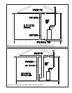
• Do not locate the terminal under decks or similar structures.
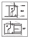
• Top of exhaust elbow, tee, or coaxial terminal must be at least 4 feet below eves, soffi ts, or overhangs. Overhang may not
exceed 3 feet (Figure 15d).
• Terminal must be at least 3 feet from an inside corner.
• Under certain conditions, water in the fl ue gas may condense on the structure in areas around the terminal. If these areas
are made of materials subject to damage by fl ue gas condensate, they should be protected.
• If possible, install the terminal on a wall away from the prevailing wind. Reliable operation of this boiler cannot be
guaranteed if the terminal is subjected to winds in excess of 40 mph.
• The noise level in the vicinity of the terminal is approximately 65 dB (roughly the level of a normal conversation). Avoid
positioning the terminal in areas where this might be objectionable.
5) Horizontal air intake terminal location - Horizontal air intake terminal must be at least 12” above the normal snow line.
6) Permitted Terminals for Vertical Venting (Vent Options 6 - 10) - Terminals used on these systems are caps. Vent
manufacturer part numbers for these caps are shown in Table 4. When Heat Fab Saf-T Vent SC is used, the 5300CI or
5400CI fi tting is used between the highest piece of Saf-T Vent CI and the cap. These fi ttings physically adapt from the
CI pipe to the cap and also provide ventilation openings which must remain open for the Saf-T Vent CI to maintain its
clearance rating.
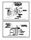
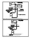
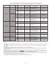
Vertical direct vent systems (Vent Options 6 - 8) can have combustion air obtained from either a vertical or horizontal air
intake system. When combustion air is obtained from the roof, the air inlet terminal consists of a 180 degree elbow (or two
90 degree elbows) with a rodent screen as shown in Figure 10. When combustion air is obtained through a horizontal vent
system, the air inlet termination is a 90 degree elbow with a rodent screen as shown in Figure 8a.
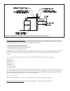
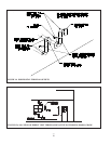
7) Permitted terminals for Vertical Coaxial Venting (Options 11 - 13) - When the Crown vertical coaxial vent kit is used (Vent
Option 11), a cap compatible with the vent system is used (Figure 12, Table 4). The concentric air intake hood supplied in
the Crown kit is the air inlet terminal (Figure 12).
When vertical coaxial venting is done using Heat Fab Saf-T Vent SC (Options 12, 13), the vent terminal is a SC03VT or
SC04VT terminal installed with a 5300CI or 5400CI adaptor. The openings in this adaptor are used for combustion air.