


8
WARRANTY NOTE: Both the temperature
sensor and moisture detection system must
be connected to the motor circuitry such that
the motor will be de-energized or sound alarm
if excessive motor temperatures are reached
and/or if water is detected in the seal chamber
and/or motor chamber. Failure to have the above
mentioned systems installed and operative,
nullifi es warranty.
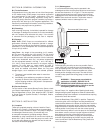
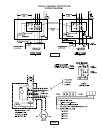
C-4.4) Overload Protection:
The normally closed (N/C) thermal sensor is embedded in the
motor windings and will detect excessive heat in the event
an overload condition occurs which will then trip and stop the
pump. The thermal sensor leads marked P1 and P2 MUST
be connected in series with the stop button of the pilot circuit
of the magnetic motor controller located in the control panel
so that the thermostat will open the circuit before dangerous
temperatures are reached. A manual momentary start switch
is required to prevent the automatic restarting of the motor
when the thermostat resets. For a typical wiring diagram,
refer to Fig. 2. In the event of an overload, the source of this
condition should be determined and rectifi ed before the pump
is put back into normal operation. DO NOT LET THE PUMP
CYCLE OR RUN IF AN OVERLOAD CONDITION OCCURS!
If current through the temperature sensor exceeds the values
listed, an intermediate control circuit relay must be used to
reduce the current or the sensor will not work properly.
TEMPERATURE SENSOR ELECTRICAL RATING
VOLTS CONTINUOUS
AMPERES
INRUSH
AMPERES
110-120 3.00 30.0
220-240 1.50 15.0
440-480 0.75 7.5
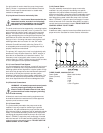
C-4.5 Moisture Sensors:
A normally open (N/O) detector is installed in the pump seal
chamber, which will detect any moisture present, and a
continuity test resistor built into the motor. The test resistor
is rated 1 watt at 330K ohms. The moisture sensors MUST
be connected to moisture detector control, which includes a
continuity test circuit, see Fig. 3 for typical wiring diagram.
The normally closed (N/C) contact of the moisture detector
MUST be connected in series with the stop button of the
pilot circuit of the magnetic motor controller. A Warrick
moisture detection control, Type 2800 is an acceptable
control if properly installed and maintained. Wiring must be
provided from the moisture detector sensor probe leads of
the motor designated W1 and W2 to terminals 9 and 10 of
the 2800-XXX control. Terminal pair 1-2 must be continuously
energized from an A-C supply line of electrical characteristics
shown on the data table. In the event of moisture detection,
the pump should be pulled and the source of the failure
located and repaired. IF MOISTURE DETECTION HAS
OCCURRED, SCHEDULE MAINTENANCE AS SOON AS
POSSIBLE!
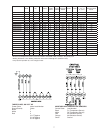
C-4.6) Control Panel and Electrical System:
The control panel and the electrical system MUST be
properly designed and wired to include at least, but not
limited to the following;
a. Proper grounding per NEC.
b. A temperature sensing circuit (see Fig. 2A & B)
c. A moisture detection circuit with continuity test
circuit (see Fig. 3)
d. An intrinsically safe level control system.
e. A main power manual disconnect and lock out.
f. A motor starter and overload system.
g. Single phase only, requires a capacitor power
pack (see Fig. 2B).
Control panels for single phase pumps MUST be purchased
from the factory and it is advisable that all three phase control
panels are also purchased from the factory.
SECTION: D START-UP OPERATION
D-1) Check Voltage and Phase:
Before operating pump, compare the voltage and phase
information stamped on the pump’s identifi cation plate to the
available power.
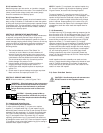
D-2) Check Pump Rotation:
Before putting pump into service for the fi rst time, the motor
rotation must be checked. Improper motor rotation can
result in poor pump performance and can damage the motor
and/or pump. To check the rotation, suspend the pump
freely, momentarily apply power and observe the “kickback”.
“Kickback” should always be in a counter-clockwise direction
as viewed from the top of the pump motor housing.
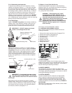
D-2.1) Incorrect Rotation for Three-Phase Pumps:
In the event that the rotation is incorrect for a three-phase
installation, interchange any two power cable leads at the
control box. DO NOT change leads in the cable housing
in the motor. Recheck the “kickback” rotation again by
momentarily applying power.
D-2.3) Test Procedure For Moisture Sensor Control:
With a Warrick moisture detection control, type 2800, a
normally closed push button and neon indicating lamp is
provided as a means of checking the moisture sensing
components. When the push button is depressed, the
indicating lamp will be illuminated to indicate (A) power is
supplied to the control, (B) the control is operative, and (C)
wiring to the moisture sensing probes in the motor is intact.
This procedure should be performed periodically to confi rm
integrity of the circuit.
D-3) Start-Up Report:
Included at the end of this manual are two start-up report
sheets, these sheets are to be completed as applicable.
Return one copy to Barnes Pumps, Inc. and store the second
in the control panel or with the pump manual if no control
panel is used. It is important to record this data at initial start-
up since it will be useful to refer to should servicing the pump
be required in the future.
D-3.1) Identifi cation Plate:
Record the numbers from the pump’s identifi cation plate on
both START-UP REPORTS provided at the end of the manual
for future reference.