


11
F-2.1) Disassembly and Inspection:
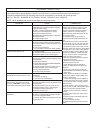
To expose outer shaft seal (13) for examination, remove
Impeller and Volute per Section F-1.1. Set motor assembly
(2) in the up position to prevent loss of oil. Remove snap
ring from motor shaft, then retaining ring (13D), spring (13C)
and rotating member (13B) from shaft, See Fig. 4. Examine
all seal parts and especially contact faces. Inspect seal for
signs of wear such as uneven wear pattern on stationary
members, chips and scratches on either seal face. DO NOT
interchange seal components, replace the entire shaft seal
(13). If replacing seal, remove stationary (13A) from mounting
plate by prying out with fl at screw driver.
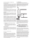
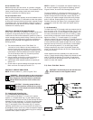
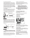
F-2.2) Reassembly:
Lightly oil (DO NOT use grease) outer surface of stationary
member (13A). Press stationary member (13A) fi rmly into
mounting plate using a seal pusher, nothing but the seal
pusher is to come in contact with seal face (see Fig. 5).
IMPORTANT ! - DO NOT hammer on the seal
pusher- it will damage the seal face.
Make sure the stationary member is in straight and that
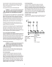
the rubber ring is not out of it’s groove. Lightly oil (DO NOT
use grease) shaft and inner surface of bellows on rotating
member (13B) see Fig. 6. With lapped surface of rotating
member (13B) facing inward toward stationary member
(13A), slide rotating member (13B) onto shaft using a seal
pusher, until lapped faces of (13A) and (13B) are together.
(see Fig. 4).
IMPORTANT! - It is extremely important to keep
seal faces clean during assembly. Dirt particles
lodged between these faces will cause the seal to
leak.
Place spring (13C) over shaft and in place on rotating
member (13B), making sure it is seated on retainer and not
cocked or resting on bellows tail. Slide retaining ring (13B)
over shaft and let rest on spring (13C). Assemble impeller
and volute as outlined in paragraph F-1.2.
F-3) Motor & Inner Shaft Seal Service
The XSE Submersible Pump motor is manufactured by
Reliance Electric Co. and must be serviced and repaired by
Reliance approved service centers only.
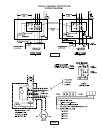
For lead reconnection information, contact Reliance Electric
Co., giving motor serial number.
WARNING ! - These motors are U/L Listed
for application in CLASS I, GROUPS C & D
EXPLOSION PROOF Environments. All repairs,
other than lead reconnects and outer seal
replacement, shall be performed by an authorized
reliance service facility. Any other repairs
performed by the customer or NON-RELIANCE
SERVICE Facilities negates the U/L Listing and
motor warranty.
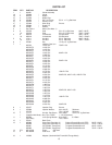
SECTION: G REPLACEMENT PARTS
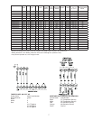
G-1 ORDERING REPLACEMENT PARTS:
When ordering replacement parts, ALWAYS furnish the
following information:
1. Pump serial number and date code. (Paragraph G-4)
2. Pump model number. (Paragraph G-3)
3. Pump part number. (Paragraph G-2)
4. Part description.
5. Item part number.
6. Quantity required.
7. Shipping instructions.
8. Billing Instructions.
G-2 PART NUMBER:
The part number consists of a six (6) digit number, which
appears in the catalog. A one or two letter suffi x may follow this
number to designate the design confi guration. This number is
used for ordering and obtaining information.
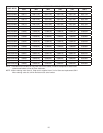
G-3 MODEL NUMBER:
This designation consists of numbers and letters which
represent the discharge size, series, horsepower, motor phase
and voltage, speed and pump design. This number is used for
ordering and obtaining information.
G-4 SERIAL NUMBER:
The serial number block will consist of a six digit number,
which is specifi c to each pump and may be preceded by
a alpha character, which indicates the plant location. This
number will also be suffi xed with a four digit number, which
indicates the date the unit was built (Date Code). EXAMPLE:
A012345 0490.
Reference the six digit portion (Serial Number) of this number
when referring to the product.
FIGURE 5
Stationary Member (13A)
Polished Face Out
Motor Mounting Plate
Seal Pusher
Rotating Member (13B)
Bullet
Reliance Motor
Seal Pusher
Stationary
FIGURE 6