


10
D-3.2) Insulation Test:
Before the pump is put into service, an insulation (megger)
test should be performed on the motor. The resistance values
(ohms) as well as the voltage (volts) and current (amps)
should be recorded on the start-up report.
D-3.3) Pump-Down Test:
After the pump has been properly wired and lowered into the
basin, sump or lift station, it is advisable to check the system
by fi lling with liquid and allowing the pump to operate through
it’s pumping cycle. The time needed to empty the system, or
pump-down time along with the volume of water, should be
recorded on the start-up report.
SECTION E: PREVENTATIVE MAINTENANCE
As the motor is Air-fi lled, no lubrication or other maintenance
is required, and generally Barnes Pumps will give very
reliable service and can be expected to operate for years of
normal sewage pumping without failing. However, as with any
mechanical piece of equipment a preventive maintenance
program is recommended and suggested to include the
following checks:
1) Test moisture detector control “Test Switch” for
continuity of circuit. Water in the seal chamber will
energize a seal leak warning light at the control panel.
This is a warning light only and does not stop the motor.
It indicates the seal has leaked and must be repaired.
This should be done within 2 or 3 weeks to prevent
further damage. See section D-2.3.
2) Inspect impeller and body for excessive build-up or
clogging and repair as required per section F-1.
3) Inspect outer shaft sealÿand replace as required per
section F-2.
4) Check motor for ground leakage and proper amp draw.
Motor and inner seal repair per section F-3.
SECTION F: SERVICE AND REPAIR
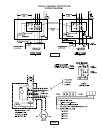
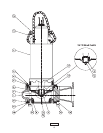
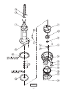
NOTE: All item numbers in ( ) refer to Figures 7 & 8.
WARNING ! - Electrical power to the pump motors
must be disconnected and locked out to prevent
any dangerous electrical hazards or personnel
danger before any service work is done to the
pump.
CAUTION ! - Operating pump builds up
heat and pressure; allow time for pump to
cool to room temperature before handling
or servicing.
F-1) Impeller and Volute Service:
F-1.1) Disassembly and Inspection:
To clean out the pump body (1), or clean out or replace
impeller (7), or replace wear ring (1F) and impeller ring (8),
disconnect power, remove hex nuts (5) and vertically lift motor
assembly from the pump body (1), and then lift out back plate
(12). Clean out the pump body, if necessary, examine wear
ring (1F) and replace if worn. If the wear ring (1F) requires
replacing, split the wear ring (1F) and remove, be careful not
to damage the suction cover (1E). Clean and examine impeller
(7) for pitting or wear, also check impeller ring (8) for scaring or
excessive wear, replace if required.
NOTE: If impeller (7) is replaced, also replace impeller ring
(8). If only the impeller ring (8) requires replacing, split the
ring and remove, be careful not to damage impeller.
To remove Impeller (7), removing cap screw (10) (or nut)
and washer (9) (and spring washer (11) if so equipped). The
impeller is keyed onto the shaft with a square key (6) and
to remove, pull impeller straight off the shaft using a wheel
puller if required. Inspect gasket (1H) if suction cover (1E)
has been removed, and replace if cut or damaged. Before
reinstallation, check the motor shaft and impeller bore for
damage.
F-1.2) Reassembly:
To install wear ring (1F) fi rst apply retaining compound to the
bore of suction cover (1E) and then press wear ring (1F) into
bore of suction cover (1E) until seated. Position gasket (1H)
on volute, and locate suction cover (1E) on volute (1), apply
thread locking compound to socket head screws (1D)ÿand
tighten into volute (1). To install impeller (7), fi rst apply
retaining compound to groove at bottom of impeller and press
impeller ring (8) on impeller (7), then apply a thin fi lm of oil
to motor shaft and slide impeller straight onto shaft, keeping
keyways lined up. Drive key (6) into keyway. Locate spacer
(9), and Lock-spring washer (11) on shaft, apply thread
locking compound to cap screw (10) threads, thread cap
screw (10) into shaft and torque to 35 ft. lbs. Rotate impeller
to check for binding.
Install impeller and motor assembly over studs and onto
volute (1). Apply thread locking compound to threads of each
stud (3). Position lockwasher (5) on studs (3) and thread
nut (4) onto stud (3) and torque to 24 ft. lbs. Check for free
rotation of motor and impeller.
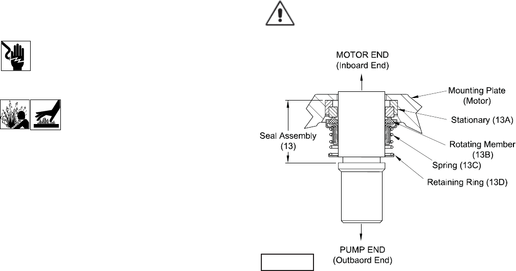
F-2) Outer Shaft Seal Service:
CAUTION! - Handle seal parts with extreme care.
DO NOT scratch or mar lapped surfaces.
FIGURE 4