


5
SECTION B: GENERAL INFORMATION
B-1) To the Purchaser:
Congratulations! You are the owner of one of the fi nest pumps
on the market today. CP&S pumps are products engineered
and manufactured of high quality components. Over one
hundred years of pump building experience along with a
continuing quality assurance program combine to produce a
pump which will stand up to the toughest applications. This
manual will provide helpful information concerning installation,
maintenance, and proper service guidelines.
B-2) Receiving:
Upon receiving the pump, it should be inspected for damage
or shortages. If damage has occurred, fi le a claim immediately
with the company that delivered the pump. If the manual
is removed from the packaging, do not lose or misplace.
B-3) Storage:
Short Term- CP&S Pumps are manufactured for effi cient
performance following short inoperative periods in storage.
For best results, pumps can be retained in storage, as factory
assembled, in a dry atmosphere with constant temperatures
for up to six (6) months.
Long Term - Any length of time exceeding six (6) months,
but not more than twenty-four (24) months. The unit should
be stored in a temperature controlled area, a roofed over
walled enclosure that provides protection from the elements
(rain, snow, wind-blown dust, etc.), and whose temperature
can be maintained between +40 deg. F and +120 deg. F.
(4.4 - 49°C). Pump should be stored in its original shipping
container. On initial start up, rotate impeller by hand to
assure seal and impeller rotate freely. If it is required that
the pump be installed and tested before the long term
storage begins, such installation will be allowed provided:
1.) The pump is not installed under water for more than
one (1) month.
2.) Immediately upon satisfactory completion of the test,
the pump is removed, thoroughly dried, repacked in the
original shipping container, and placed in a temperature
controlled storage area.
B-4) Service Centers:
For the location of the nearest Barnes Service Center, check
your Barnes representative or Crane Pumps & Systems, Inc.,
Service Department in Piqua, Ohio, telephone (937) 778-8947
or Crane Pumps & Systems Canada, in Brampton, Ontario,
(905) 457-6223.
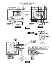
SECTION C: INSTALLATION
C-1) Location:
These self-contained pumping units are Listed for Class I,
Groups C & D, Division 1 locations and are recommended
for use in a sump, lift station or basin. This pump is designed
for submerged continuous duty (15 minutes duty in air
at nameplate horsepower), pumping sewage, effl uent,
wastewater or other nonexplosive or noncorrosive liquids not
above 104°F (40°C). Never install the pump in a trench, ditch
or hole with a dirt bottom; the legs will sink into the dirt and
the suction will become plugged.
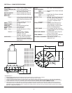
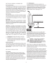
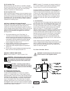
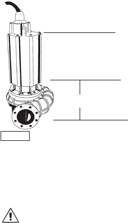
C-1.1) Submergence:
It is recommended that the pump be operated in the
submerged condition and the sump liquid level should never
be less than dimension “A” in Figure 1. The time required
to draw the well down from top of motor to the minimum
submergence level should not be greater than 15 minutes.
NOTE: Outer shaft seal must be in liquid when motor is
operated, whether motor is submerged or in air.
C-2) Discharge:
Discharge piping should be as short as possible. Both a
check valve and a shut-off valve are recommended for
each pump being used. The check valve is used to prevent
backfl ow into the sump. Excessive backfl ow can cause
fl ooding and/or damage to the pump. The shut-off valve
is used to stop system fl ow during pump or check valve
servicing.
WARNING ! - These pumps are suitable for
application in CLASS I, GROUPS C & D,
HAZARDOUS LOCATIONS and require a non-
sparking break away fi tting. Failure to use the
non-sparking BAF voids warranty.
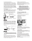
Barnes Pumps, Inc. supplies a Non-Sparking break away
fi tting discharge system designed to allow the submersible
wastewater pump to be installed or removed without requiring
personnel to enter the wet well.
Place the Break Away Fitting (BAF) in position. Temporarily
secure the guide rails in the upper mounting brackets and
locate the base elbow on the bottom of the wet well. Level the
base elbow with grout and/or shims. Install the intermediate
support brackets, if required. Make sure the rails are in a true
vertical position so the pump will clear the access opening
and will slide freely down the rails into place on the discharge
base elbow. once the rails are in proper alignment, bolt the
base elbow into the fl oor of the station and connect the
discharge pipe to the elbow. Connect the movable portion
and other supplied fi ttings of the BAF onto the pump and
lower into wet well. See the Break Away Fitting manual for
more information.
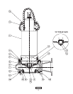
FIGURE 1
Recommended Submergence
Level
Minimum Submergence Level
Bottom of Feet
A = 12”