


1
2
3
4
5
Contents
A
CPG #2561255 FIRELARM 2500 Operating Manual
A-4
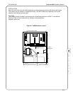
A.4 Master Box Module (Model MBM)
UL LISTED: For use with the FireLarm 2500
Part No. 345-0235
Power requirements:
Standby: 30mA Max @24VDC
Alarm: 300 mA Max @24VCD
Master Box Coil Resistance: 14.5 ohms
Trouble output: Positive 2.5 V goes low in trouble and SPDT contacts transfer.
Contacts rated 2A@30VDC
Visual indicators: Yellow - Trouble/Disable
Yellow - Reset supervisory/ contacts off normal
Disable capability: Switch provided (can be made inoperative)
Size: 3"x5-1/2"
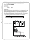
The Model MBM is a local energy type Master Box actuating module for use with the FireLarm 2500 Fire
Control Panel. The unit can be mounted in the control panel housing, if space is available, or in a
separate housing (CPG #327-0089). The circuit between the module and the master box is supervised to
detect an open circuit. Terminals are provided for the connection of the master box reset supervisory
contacts.
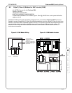
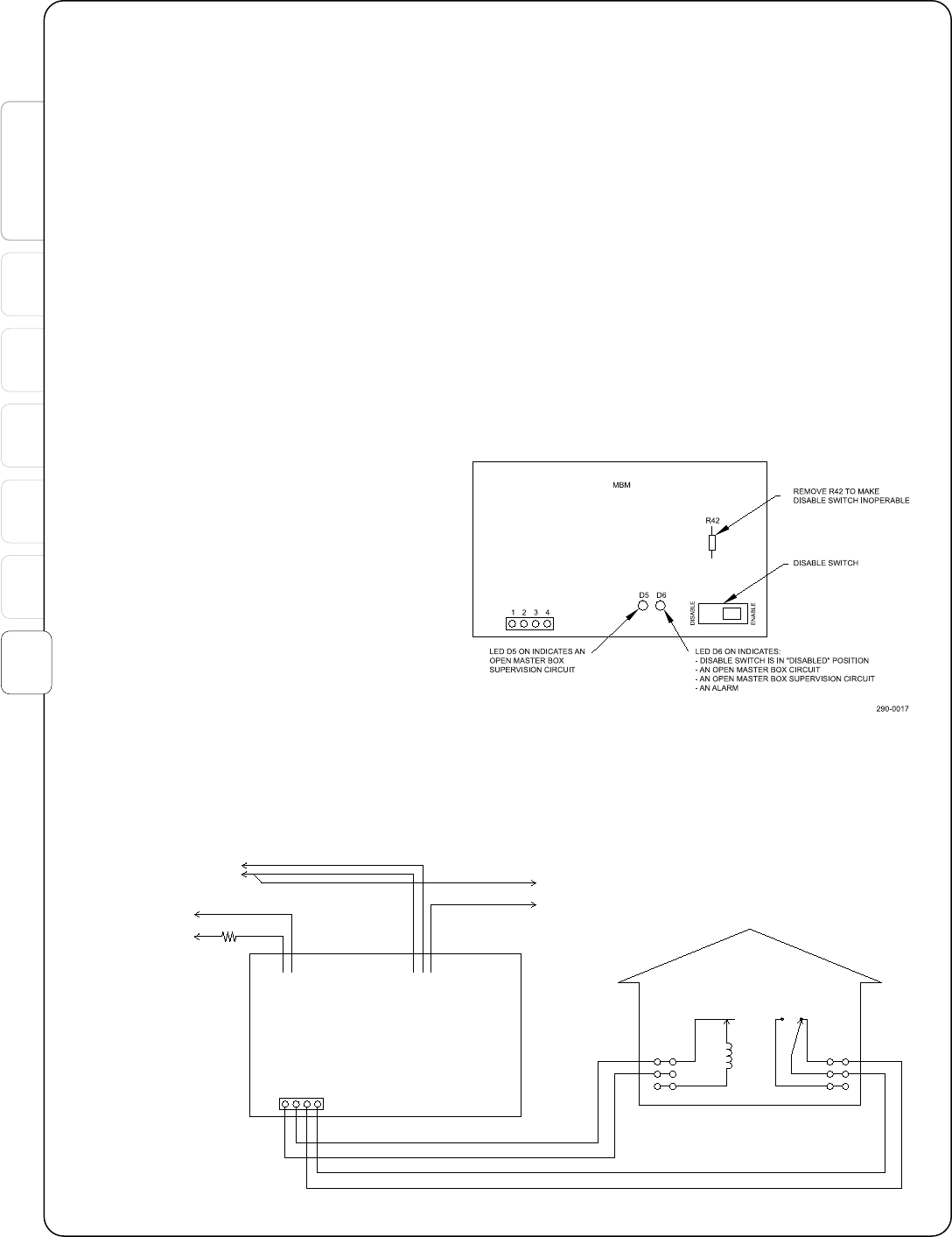
A switch is provided to disable the unit so
that it will not trip the master box. Operation
of this switch will cause LED (D6) to
illuminate. To make this switch inoperative,
remove R42.
If the master box is provided with reset
supervisory contacts, the position of these
contacts may be supervised. When these
contacts are off normal LED D5 will
illuminate and the trouble outputs will be
activated.
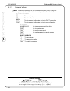
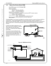
24VDC
.3A MAX.
N.O. (TERMINAL 31)
COM (TERMINAL 30)
TO AUXILIARY
ALARM CONTACTS
CONTACTS SHOWN
IN NORMAL STANDBY
CONDITION
HARRINGTON
OR GAMEWELL
MASTER FIRE
ALARM BOX
TRIP COIL
ORANGE ORANGE
RED
ORANGE
BLUE
WHITE
OPTIONAL RESET
SUPERVISION
CONTACTS
COM - (TERMINAL 43)
TERMINAL 13
TERMINAL 14
290-0016
CONNECT INTO
SUPV. CIRCUIT
WITH 5.1K OHM
END-OF-LINE
RESISTOR (#024-4556)
AUX PWER + (TERMINAL 44)
RED
GREEN
YELLOW
5.1K
1234
BLACK
YELLOW
MBM
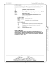
Figure A-5. MBM.
Figure A-6. MBM Module Wiring.