


E
D
C
B
5
A
4
CPG #2561255 FIRELARM 2500 Operating Manual
4-1
4 Configuration and Programming
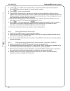
4.1 Selecting connected device options (DIP switches)
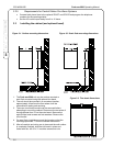
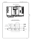
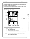
A series of DIP switches are used to configure devices connected to the fire alarm control panel. DIP
switches are located in the lower right corner of the panel.
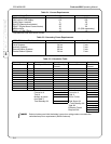
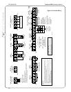
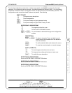
DIP Switch 9 Description of Disabled States
(Switch to left side)
Description of Enabled States
(Switch to right side)
1. B1 Strobe NAC 1 devices are silenceable. NAC 1 devices are non-silenceable –
requires panel reset to silence.
2. B1 Temporal NAC 1 rings constant NAC 1 rings for 3 pulses and then stops
for 1 pulse (1/2 second per pulse)
3. TRBL-REM ALM Remote alarm trouble disabled. Remote alarm trouble enabled.
4. ANNUNC DISC Remote annunciator is not used or
annunciator input is ignored.
Remote annunciator is used and
annunciator input is accepted.
5. Z1- Waterflow Zone not waterflow switch (silenceable) Zone waterflow switch (not silenceable)
6. Z1- Verify Zone not verify Zone verify
7. Z1- Class A Zone Style B (Class B) Zone Style D (Class A)
8. Z2- Waterflow Zone not waterflow switch (silenceable) Zone waterflow switch (not silenceable)
9. Z2-Verify Zone not verify Zone Verify
10. Z2- Class A Zone Style B (Class B) Zone Style D (Class A)
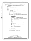
DIP Switch 10 Description of Disabled States
(Switch to left side)
Description of Enabled States
(Switch to right side)
1. Z3- Waterflow Zone not waterflow switch (silenceable) Zone waterflow switch (not silenceable)
2. Z3- Verify Zone not verify Zone verify
3. Z3- Class A Zone Style B (Class B) Zone Style D (Class A)
4. Z4- Waterflow Zone not waterflow switch (silenceable) Zone waterflow switch (not silenceable)
5. Z4- Verify Zone not verify Zone verify
6. Z4-Class A Zone Style B (Class B) Zone Style D (Class A)
4.1.1 B1 Strobe device
Place the B1 STROBE switch in the “on” position (right side of the switch) when NAC 1 is a non-
silenceable circuit (for devices such as strobes). When enabled, the circuit cannot be silenced during
alarm except by resetting the panel.
4.1.2 B1 Temporal pattern
Place the B1 TEMPORAL switch in the “on” position (right side of the switch) when you wish NAC 1 to
ring a temporal pattern. A temporal signal consists of three rings and one pause as defined by NFPA 72,
Section A-3-7.2 (2).
Figure 4-1. DIP Switches