


Contents
1
2
3
CPG #2561255 FIRELARM 2500 Operating Manual
3-6
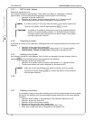
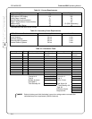
POWER RATING
120VAC - 60 HZ
(2) 12V, 6.5 AH min. batteries are required.
Maximum battery charge current: 1A
The battery set must be replaced every 4 years or earlier if capacity is
excessively reduced. The batteries should be checked at least twice a
year, or more often if required by local codes.
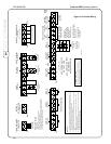
SEE ZONES 1 AND 2 AND BELL 1
FOR TYPICAL CONNECTIONS
5.1K
TB2 TB1A
19
(+)
20
(+)
21
(-)
22
(-) (+) (+) (-) (-)
5.1K 5.1K
N.O. COM N.C. N.O. COM N.C.
23
(+)
29
(+)
30
(-)
31
(-) (+) (+) (-) (-)
32
(+)
33 3424 25 26 27 28
(-) (+) (-)(-) (+)(+) (-)
38 39 4035 36 37
(+) (-) (+)
42 43 4441
ZONE 3
(SUPERVISED)
ZONE 4
(SUPERVISED)
BELL 2
(SUPERVISED)
AUXILIARY
ALARM
(NOT SUPERVISED)
USE POWER LIMITED
CIRCUITS ONLY.
AUX. CONTACTS RATED
2A @ 30VDC
0.6 POWER FACTOR
TYPICAL
STYLE Y (CLASS B)
WIRING
USE POLARIZED
DEVICES ONLY
24VDC 2A MAX
AUXILIARY
TROUBLE
REMOTE STATION
E
GND
SECONDARY
WINDING OF
TRANSFORMER
BATT TB1 TB4P2
TRANSFORMER
CONNECTOR
BATTERY
CONNECTOR
(SUPERVISED)
ZONE 1
(SUPERVISED)
ZONE 2
(SUPERVISED)
SUPERVISORY
(SUPERVISED)
BELL 1
(SUPERVISED)
24VDC
SEE NOTE 6
24VDC .015A MAX
EACH CIRCUIT
ALARM
RA
(SUPERVISED*)
SUPERVISORY
RS
(SUPERVISED*)
4-WIRE
DET. PWR
(SUPERVISED)
AUX.
PWR
REMOTE ANNUNCIATOR
(SUPERVISED)
(2 MAX, 100mA PER UNIT)
TYPICAL
STYLE D (CLASS A)
WIRING
USE N.O. SUPV
SWITCHES
INTENDED FOR
CONNECTION TO A
POLARITY REVERSAL
CIRCUIT OF A REMOTE
STATION RECEIVEING
UNIT THAT HAS
COMPATIBLE RATINGS.
AN ECLIPSE MODEL FA24VB
MUST BE USED ON REMOTE
STATION CIRCUITS.
* THE REMOTE STATION
MUST PROVIDE
SUPERVISION
REMOTE ANNUNCIATOR
TYPICAL
STYLE B (CLASS B)
WIRING
5.1K 5.1K
5.1K
290-0008
D D* GND +24V EARTH
(OPTIONAL)
(+) (-)
34 567891011121314 15161718E34
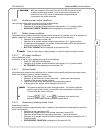
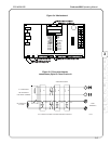
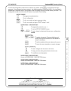
POWER LIMITED
All circuits powered by this panel are power limited.
Transformer, battery, auxiliary alarm and auxiliary trouble
connections are not power limited.
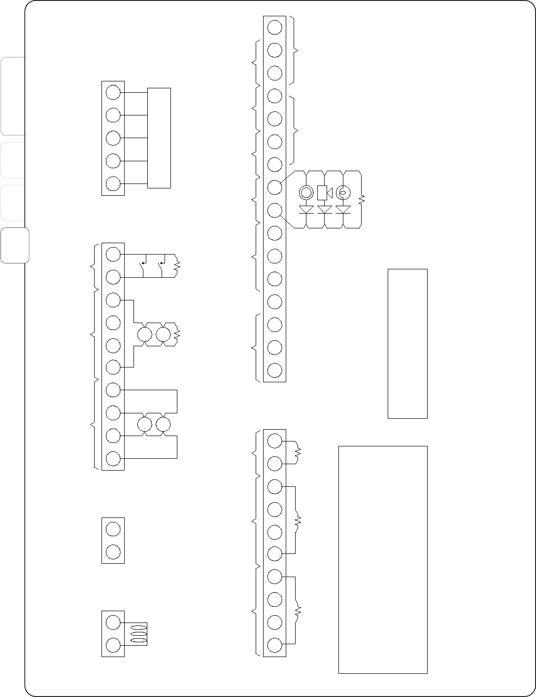
NOTES:
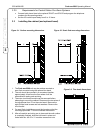
1) Use only smoke detectors that are listed in compatibility listing in owner's manual.
2) Any zone (except supervisory zone) can be operated in a Style D (Class A) mode. The
end-of-line resistor is in the panel when Class A mode is used.
3) Leave end-of-line test resistors on unused circuits.
4) Combined load of all external devices, including indicating appliances, is not to exceed
2.5A.
5) Polarities shown are for normal standby condition. Bell and remote station circuits
reverse polarity when activated.
6) Combined load of remote annunciator, 4-wire detectors, and auxiliary power (terminals
17, 18, 42, 43, and 44) is not to exceed .5A.
7) All EOL resistors are 5.1K ohms (#024-4556)
Figure 3-6. Device Wiring